
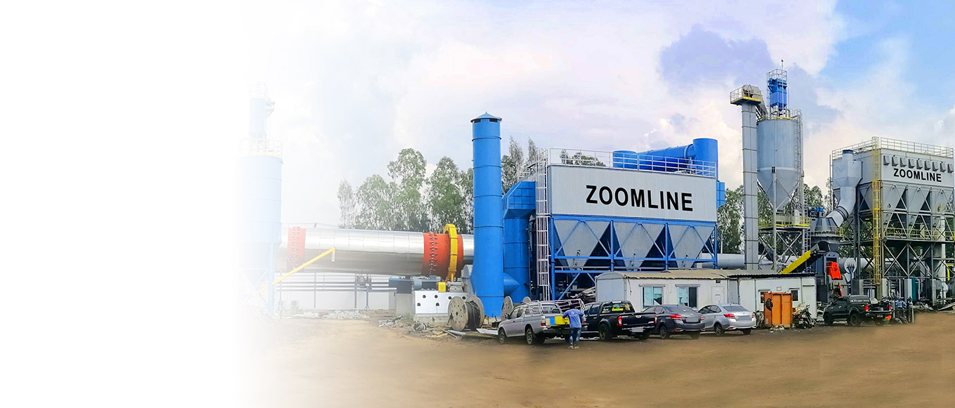
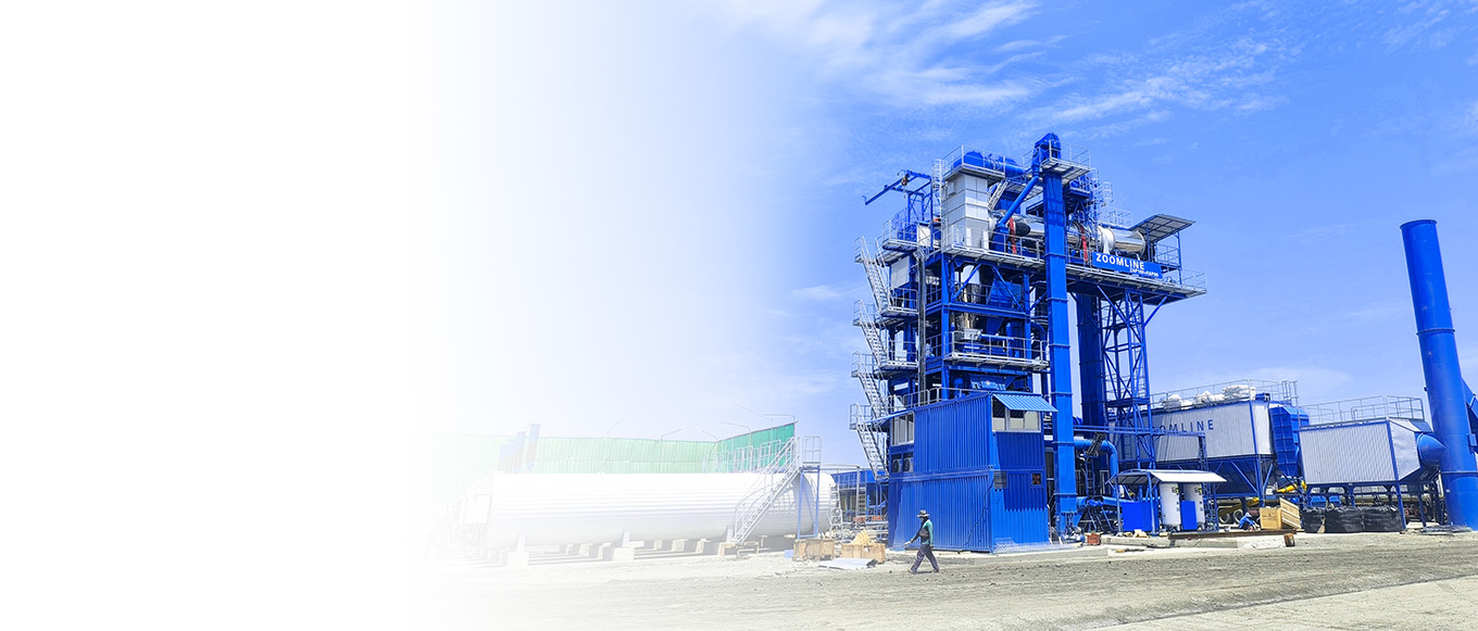
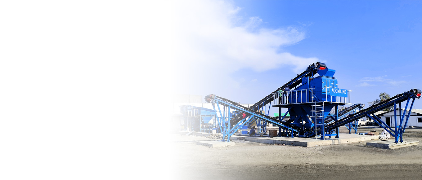
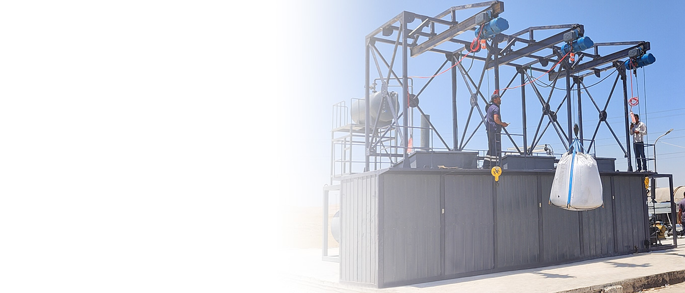



How does an asphalt mixing plant produce hot-mixed asphalt? 2026 complete process and operation guide
In modern road construction, Hot Mix Asphalt (HMA) is the most core paving material for highways, airports, and municipal roads, and its quality directly affects the durability, flatness, and service life of the road surface. The asphalt mixing plant is the core equipment for producing Hot Mix Asphalt, which accurately controls the proportion and temperature of aggregates, asphalt, mineral powder, and other raw materials to uniformly mix them into hot mix asphalt mixtures that meet construction requirements.
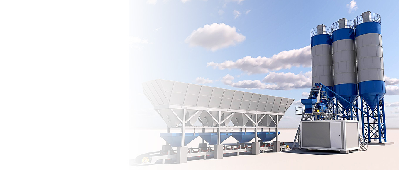
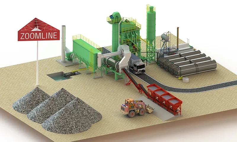
The main production process of asphalt mixing plants producing Hot Mix Asphalt includes cold material supply, aggregate drying and heating, measurement and proportioning, mixing, discharge, and flue gas treatment. According to different mixing methods, it is mainly divided into two types: batch mix (Batch Mix) and continuous drum mix (Drum Mix). The batch mix is highly flexible and has excellent proportioning accuracy, suitable for high-grade highways and projects with frequent formula changes; the continuous mix has high production efficiency and a compact structure, especially suitable for large-scale stable production and rapid site change scenarios.
In 2026, with the upgrading of environmental protection standards and the popularization of intelligent technology, asphalt mixing plants are developing towards low energy consumption, low emissions, and intelligence. This article will systematically introduce the complete production process, key parameter control, best practices, and the actual application of Zoomline asphalt mixing equipment for Hot Mix Asphalt production, to help construction units and equipment users master scientific production methods and improve project efficiency and quality.
Core Process Flow of Hot Mix Asphalt Production in Asphalt Mixing Plant
The production of hot mix asphalt in asphalt mixing plants generally involves the following 7 main steps:
1. Cold Material Supply and Primary Mixing
Different sizes of cold aggregates (0-5mm, 5-10mm, 10-20mm, etc.) are stored separately in multiple cold material bins. Through variable frequency feeders, the materials are fed uniformly at a set ratio, and then transported into the drying system by conveyer belts. In this stage, the moisture content and gradation of aggregates need to be controlled to avoid excessive drying energy consumption in subsequent processes.
2. Aggregate Drying and Heating
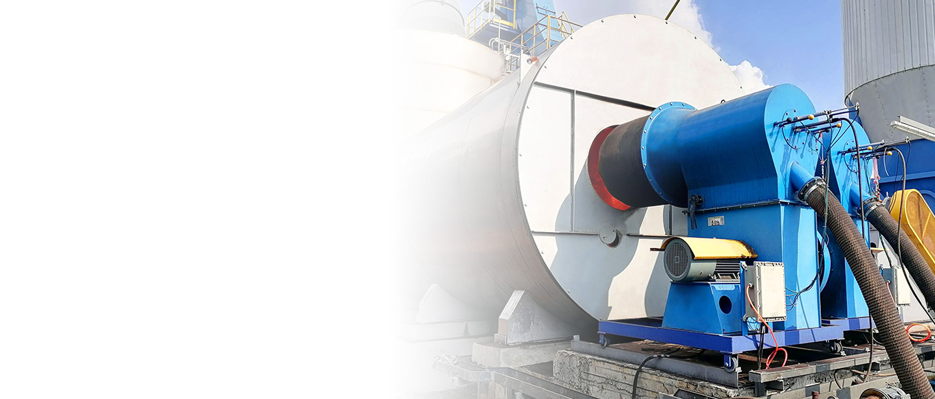
Cold aggregates enter the drying drum (or drying cylinder), and are dried and heated by the high-temperature hot gas produced by burners, raising the temperature of aggregates to 150-180°C and reducing the moisture content to less than 0.5%.
Intermittent mixing plants usually use independent drying drums;
Continuous drum mixing plants (such as Zoomline ZAP-C series) integrate the drying and mixing processes partially in the same drum, with a more compact structure.
3. Hot Aggregate Screening and Temporary Storage (mainly applicable to intermittent mixing plants)
Heated aggregates are sent to the screening layer by a hot elevator, precisely screened into different specifications according to particle size, and stored in corresponding hot material bins, preparing for accurate measurement in the next step.
4. Accurate Measurement and Proportioning
Aggregates, asphalt, and mineral powder are measured by high-precision electronic scales (aggregates accuracy ±0.5%, asphalt accuracy ±0.3%). The system automatically adjusts the proportions of each component according to the set formula, ensuring that key indicators such as asphalt content are stable.
5. Mixing Process
Intermittent: Hot aggregates are first dry mixed (10-15 seconds), then hot asphalt is sprayed in for wet mixing (35-50 seconds), with a total mixing time of about 45-60 seconds, ensuring the uniformity of the mixture and the absence of speckled materials.
Continuous Drum: Aggregates are continuously mixed with asphalt and mineral powder at the rear end of the drum, with an uninterrupted production process, higher efficiency, and suitable for large-scale stable formula production.
6.Finished Product Discharge and Storage
The mixed hot mix asphalt is discharged through the discharging door or conveyor belt into an insulated finished product bin for temporary storage, or directly loaded onto trucks for transportation. The discharge temperature must be strictly controlled within the range of 140-170°C to avoid asphalt aging due to excessive temperature or affecting construction and workability due to low temperature.
7. Flue Gas and Dust Treatment
The flue gas and dust produced during the drying and combustion processes are treated by high-efficiency bag dust collectors or wet dusting systems to ensure that emissions meet national and local environmental protection standards.
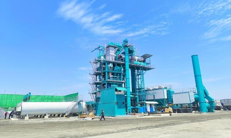
Zoomline asphalt mixing plants (including fixed and super mobile ZAP-C series) use advanced control systems in all stages, which can realize automatic operation, real-time monitoring, and rapid adjustment, significantly improving production stability and environmental performance.
Crude Oil Distillation and Heavy Residue Extraction
The desalted clean crude oil then enters the distillation (fractionation) process — This is the critical step for separating bitumen precursors (heavy residue) from crude oil. It operates on the principle of “differences in boiling points among hydrocarbon compounds,” achieving complete separation of light fractions (gasoline, diesel) from heavy fractions (asphalt feedstock) through heating and precise separation within the fractionation tower.
Crude Oil Preheating for Waste Heat Recovery and Energy Optimization
Desalted crude oil is first conveyed from the desalting tank to the “preheating system” via a “feed pump” (head: 50-100 meters; flow rate adjusted per production capacity). This system comprises 3-5 series-connected “shell-and-tube heat exchangers,” whose core function is to utilize “waste heat” generated in subsequent production processes to preheat the crude oil, achieving energy recycling:
First-stage heat exchanger: Exchanges heat with light hydrocarbon vapors (approx. 200-300°F) discharged from the top of the fractionation tower, raising crude oil temperature from 93-149°C to 150-200°C;
Second-stage heat exchanger: Exchanges heat with diesel and jet fuel drawn from sidestreams (temperature approx. 300-400°F), further raising crude oil temperature to 250-300°C;
Third-stage heat exchanger: Heat exchange with heavy residues from the bottom of the fractionation tower (temperature approximately 700-800°F), ultimately raising crude oil temperature to 550°F (approximately 288°C).
Through this preheating process, the crude oil recovers 60%-70% of the system’s residual heat, reducing subsequent furnace fuel consumption by over 30%. This approach saves energy and cuts carbon emissions—for example, in a plant producing 1,000 tons of asphalt daily, the preheating system saves approximately 5,000 cubic meters of natural gas consumption per day.
High-Temperature Furnace Heating Provides Vaporization Power for Crude Oil
The preheated crude oil is fed into the “tube furnace”—the “heart” of the distillation process. The furnace consists of a burner, radiation chamber, and convection chamber: • Burner: Natural gas or fuel oil is introduced and combusted within the radiation chamber, generating a high-temperature flame of 1200-1400 degrees Celsius;
Radiation Chamber: Crude oil flows through furnace tubes (diameter 100-150 mm, made of heat-resistant alloy steel) within the radiation chamber, directly absorbing radiant heat from the flames to rapidly reach temperatures of 700°F (approximately 371°C);
Convection Chamber: Furnace tubes extend into the convection chamber, absorbing convective heat from combustion exhaust gases to supplement heating, ensuring crude oil vaporization exceeds 50%. During heating, the crude oil flow velocity within the furnace tubes must be strictly controlled between 1.5–2.5 meters per second. Excessively low flow rates cause localized overheating, leading to coking of heavy crude components (which adhere to the tube walls and impair heat transfer).
Conversely, excessively high flow rates result in insufficient heating and inadequate vaporization rates. Therefore, the heater is equipped with a “Flow Rate Monitor” and a “Coking Early Warning System” to continuously monitor furnace tube temperature and pressure. Upon detecting anomalies, the burner load or crude oil flow rate is immediately adjusted.
Precision Separation in the Distillation Column Transforms Mixtures into Pure Components
The high-temperature gas-liquid mixture (with 50%-60% crude oil vaporization rate) is conveyed to the “distillation column” — — a cylindrical tower 20–40 meters tall with a diameter of 3–6 meters. Its interior houses 30–50 layers of “bubble cap trays” (or floating valve trays), while the exterior is wrapped in insulation (100–150 mm thick) to maintain stable temperature gradients within the tower. The separation process within the distillation column relies on “countercurrent gas-liquid heat and mass transfer,” occurring in four distinct steps:
Initial Gas-Liquid Distribution: The high-temperature gas-liquid mixture enters through the “feed inlet” at the bottom of the column. Due to their higher density, liquid components fall directly to the column base, while gaseous components rise upward, entering the first tray (near the bottom). Temperature within the tower exhibits a downward gradient: approximately 700-750°F (371-399°C) at the bottom and 150-200°F (66-93°C) at the top. Temperature decreases by 5-10°F per tray level ascended — — this temperature gradient is the core condition for achieving component separation.
Heat and Mass Transfer in Bubble Cap Trays: Each tray features “bubbles” (diameter 50-80 mm, made of cast iron or stainless steel). A 5-10 mm gap exists between the bubble base and the tray. The tray also incorporates an “overflow weir,” maintaining a liquid layer 50-100 mm high (referred to as the “liquid bed”). As gaseous components flow upward, they must pass through the gap beneath the bubbles to enter the liquid layer, forming numerous bubbles (diameter 1-5 mm). These bubbles undergo extensive contact with the liquid layer, facilitating intense heat and mass transfer:
Heat transfer: The gaseous components, being hotter than the liquid layer, transfer heat to the liquid through the bubbles, lowering their temperature.
Mass transfer: Heavy hydrocarbons with higher boiling points (e.g., heavy diesel, lubricating oil components) condense into liquid due to cooling and remain in the liquid layer of the current tray; light hydrocarbons with lower boiling points (e.g., gasoline components) vaporize by absorbing heat and continue upward with the gas stream.
Component Enrichment and Side-Stream Extraction: As the gas stream ascends through each tray, its light component content increases incrementally; conversely, the liquid stream descends through each tray, increasing its heavy component content incrementally—this process is termed “component enrichment.” When the concentration of a specific component (e.g., diesel, jet fuel) in the liquid layer of a given tray reaches over 90%, it is extracted via a “side-line withdrawal pipe” (diameter 80-120 mm) and sent to subsequent refining units (e.g., hydrodesulfurization, dewaxing) for processing into finished products. Light components at the tower top (e.g., gasoline, liquefied petroleum gas) are discharged as vapors, cooled into liquids in condensers for collection; uncondensed “dry gas” (methane, ethane, etc.) at the tower top is flared (or recovered as fuel).
Formation and Extraction of Heavy Residue: The bottom temperature of the fractionation tower is maintained at 800°F (approximately 427°C) or higher. At this temperature, the heaviest hydrocarbons in crude oil with the highest boiling points (such as asphaltenes, resins, and long-chain alkanes) cannot vaporize and instead settle as liquids at the tower bottom, forming “heavy residue”— — with a density of 1.01–1.05 g/cm³ and viscosity (at 100°C) of 1000–5000 cP. This residue serves as the core feedstock for asphalt production. The heavy residue is extracted via a “residue pump” (made of wear-resistant alloy, with a head of 80-120 meters) at the tower bottom and sent to subsequent asphalt processing stages. The tower bottom also features an “anti-coking agitator” to prevent coking caused by prolonged stagnation of the heavy residue, ensuring continuous and stable extraction.
During distillation, the “cut point” is a critical parameter for controlling heavy residue quality. Each fraction (component) has corresponding “Initial Boiling Point” (IBP) and “End Boiling Point” (EP): the IBP is the lowest temperature at which the fraction begins vaporizing, while the EP is the highest temperature at which the fraction fully vaporizes. For asphalt feedstock (heavy residue), the cut point is set as “Final Boiling Point ≥ 800°F.” If the cut point is too low, excessive light components contaminate the heavy residue, reducing asphalt viscosity and compromising high-temperature stability. Conversely, an excessively high cut point causes excessive coking of the residue, increasing asphalt brittleness. Therefore, the fractionation tower is equipped with an “online gas chromatograph” to analyze the composition of each tray in real time. By adjusting the furnace temperature and reflux ratio (the ratio of tower top reflux liquid to side-line withdrawal), the cut point is precisely controlled to ensure the stability of the heavy residue composition.
Refined Processing of Residue into Finished Asphalt Products
The heavy residue obtained from the bottom of the fractionation tower possesses the fundamental characteristics of asphalt. However, it still requires refined processing—including “heated dehydration, blending modification, and homogenization mixing”—to transform it into finished asphalt products tailored to different engineering requirements. This stage is the core of asphalt performance “customization,” directly determining the application scenarios and engineering outcomes of the asphalt.
Heating and Dehydration: Eliminating Hazards and Ensuring Density
Heavy residue typically contains 0.1%-0.5% residual moisture (primarily from water not fully separated during distillation). If this moisture remains in the asphalt, it vaporizes and expands during subsequent construction processes (such as high-temperature compaction during asphalt pavement laying), forming bubbles that cause defects like “honeycombing” and “cracking,” severely impacting pavement lifespan. Therefore, asphalt plants must achieve complete dehydration using a “heated dehydration tank”:
Heating and Temperature Rise: Heavy residue is fed into a jacketed heating dehydration tank. Steam (pressure 0.8-1.2MPa, temperature 170-190°C) is circulated through the jacket, indirectly heating the residue to 280-300°C — — This temperature facilitates rapid water vaporization while preventing excessive aging of the bituminous material.
Negative Pressure Dehydration: A vacuum pump connected to the top of the dehydration tank reduces the internal pressure to -0.08 to -0.09 MPa (negative pressure state). This lowers the boiling point of water (by approximately 50-60°C), accelerating vaporization. The vaporized water is cooled into liquid form by a condenser, collected, and sent to the wastewater treatment system.
Moisture Detection: During dehydration, an “online moisture analyzer” continuously monitors residual moisture content. Dehydration is complete when moisture ≤0.05%—the resulting residue is termed “base asphalt,” possessing fundamental bonding and waterproofing properties suitable as raw material for standard road asphalt.
Customized Asphalt Performance Enhancement Through Blending Modification
As infrastructure demands increasingly stringent asphalt performance requirements, base asphalt undergoes performance upgrades via “modifiers” to form “modified asphalt.” The modification process at asphalt plants occurs within “modification mixing tanks.” Its core principle involves precisely controlling the ratio, temperature, and mixing intensity to ensure uniform blending of the modifier with the base asphalt, thereby maximizing the modification effect. Common modification processes include:
Rubber Powder Modified Asphalt
Modifier: Waste tire rubber powder (particle size 20-40 mesh, content 15%-25% by mass of base asphalt);
Mixing process: Base asphalt heated to 180-200°C, rubber powder added, then sheared for 15-20 minutes using a “high-speed shear mixer” (3000-5000 rpm). Shearing breaks rubber particles and disperses them into the asphalt. The elastomer components in the rubber powder form a “network structure” with the asphalt, enhancing its elastic recovery rate (from 30% to over 70%) and rutting resistance (dynamic stability at 60°C increases from 1000 cycles/mm to over 3000 cycles/mm).
SBS Polymer Modified Asphalt (for High/Low Temperature Stable Pavements)
Modifier: Styrene-Butadiene-Styrene Block Copolymer (SBS, granular, 3%-5% by mass of base asphalt);
Mixing Process: Heat base asphalt to 190-210°C, add SBS granules, and initially swell SBS via “low-speed stirring” (500-1000 rpm) for 10-15 minutes. Then perform forced mixing using a “twin-screw extruder” (200-300 rpm) — — The screw shear action within the extruder fully dissolves and disperses SBS into nanoscale particles, forming an “interpenetrating network structure” with the asphalt. This simultaneously enhances the asphalt’s high-temperature rutting resistance (60°C dynamic stability ≥4000 cycles/mm) and low-temperature crack resistance (-10°C low-temperature elongation ≥50cm), suitable for northern cold regions and heavy-duty highways. 3. Epoxy-modified asphalt (for airport runways) o Modifier: Epoxy resin (liquid, 5%-8% by mass of base asphalt) with curing agent (amine, mixed 1:1 with epoxy resin) o Mixing process: Base asphalt heated to 160-180°C. First add epoxy resin, stir for 5-10 minutes, then add curing agent and continue stirring for 3-5 minutes — — The curing agent undergoes a cross-linking reaction with the epoxy resin, forming a “rigid network structure.” This significantly enhances the asphalt’s compressive strength (from 15MPa to over 30MPa) and impact resistance, while simultaneously increasing the surface friction coefficient to over 0.6. This meets the stringent requirements for high load-bearing capacity and skid resistance demanded by airport runways.
Temperature control is critical during modifier mixing — insufficient temperatures cause incomplete modifier dissolution, leading to “particle agglomeration” that compromises asphalt performance uniformity; excessive temperatures induce thermal-oxidative aging of modifiers (especially polymer-based ones), nullifying their intended modification effects. Therefore, the modified mixing tank is equipped with a “dual-path temperature control system”: one path maintains the base temperature via steam heating through the jacket, while the other path uses an internal cooling coil for real-time temperature adjustment, ensuring temperature fluctuations during mixing are controlled within ±5 degrees Celsius.
Mixing and Finished Product Storage
After modification mixing, the asphalt enters a “homogenizing mixer” for secondary mixing to further eliminate local component variations. Homogenization employs an “anchor-type agitator” (rotation speed 50-100 rpm), typically operating for 20-30 minutes to ensure asphalt-modifier mixing uniformity exceeds 95% — — Homogeneity is verified through “sampling inspection.” Randomly collected asphalt samples from different tank locations must show deviation in viscosity, elastic recovery rate, and other indicators ≤5% to be deemed homogeneous.
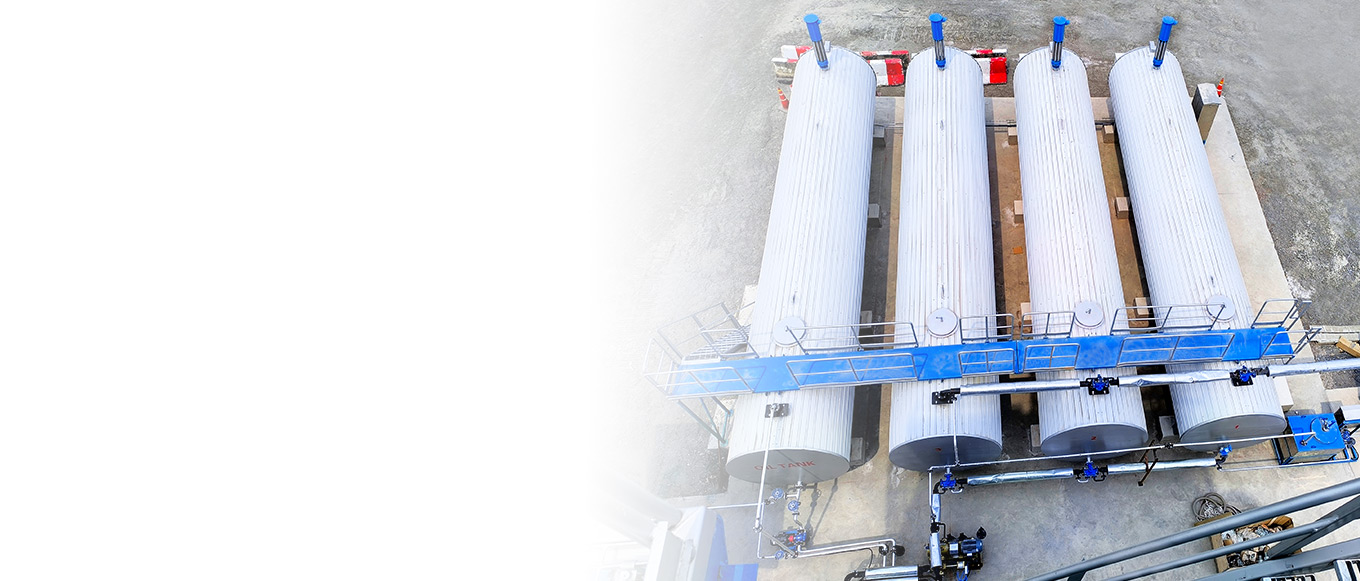
Qualified finished asphalt is conveyed to an “insulated storage tank” for temporary holding. These tanks are typically vertical cylindrical structures (500-2000 cubic meters capacity) featuring a “double-walled stainless steel + insulation layer” design: an inner layer of 304 stainless steel (8-12 mm thick), with an outer layer of carbon steel (5-8 mm thick). The intermediate space is filled with rock wool or polyurethane insulation (150-200 mm thick), ensuring the asphalt temperature within the tank is maintained at 150-180°C (adjusted according to asphalt grade) to prevent cooling and solidification. The tank top features a “breather valve” to equalize internal pressure and prevent accumulation of asphalt vapor. A “heating coil” is installed at the bottom; for long-term storage, low-pressure steam can be used for gradual heating to maintain asphalt fluidity.

Full-Process Precision Quality Control for Asphalt
Asphalt quality directly impacts project safety and service life. Therefore, the asphalt plant implements a comprehensive “pre-production, in-production, post-production” quality control system. Through specialized laboratories, automated monitoring equipment, and standardized testing procedures, every batch of asphalt meets national standards (e.g., GB/T 15180-2017 “Petroleum Asphalt for Heavy Traffic Roads”) or customized client requirements.
Strict Raw Material Quality Control
Crude Oil Quality Testing: Upon arrival of each crude oil batch, the laboratory tests its density (at 20°C), viscosity (at 100°C), salt content, moisture content, and asphaltene content. Only crude oil meeting ≤10 lbs/1000 barrels salt content and ≥15% asphaltene content proceeds to desalting. If specifications are not met, negotiate returns with suppliers or blend adjustments (e.g., mixing high-salt and low-salt crude proportionally to reduce overall salt content).
Modifier Quality Verification: Upon arrival, modifiers must be verified for type, purity, and shelf life. For example: – SBS modifiers require testing for styrene content (typically 28%-32%) and melt index (≤5g/10min at 190°C / 2.16kg). Rubber powder must be tested for ash content (≤8%) and fiber content (≤0.5%) to ensure modifiers meet production formula requirements.
Real-Time Monitoring and Parameter Control
Desalting Process Monitoring: Install an “online salt content analyzer” and “moisture detector” at the desalting tank outlet to continuously monitor post-desalting crude oil’s salt content (≤5 lbs/1000 barrels) and moisture content (≤0.2%). If metrics exceed limits, immediately adjust water injection volume, demulsifier dosage, or electric field strength until compliance is achieved.
Distillation Monitoring: Install “temperature sensors” and “pressure transmitters” at the top, middle, and bottom of the fractionation tower. Data is transmitted in real time to the central control system: Top temperature must be stable between 150-200°F, bottom temperature must be maintained above 800°F, and tower pressure must be controlled between 0.1-0.12 MPa (atmospheric distillation). Simultaneously, an “online gas chromatograph” analyzes the composition of side-stream fractions to ensure precise cutting points for heavy residues (final boiling point ≥800°F).
Modification Process Monitoring: During the modification mixing process, samples are taken every 5 minutes to to measure asphalt viscosity (at 135°C, must meet grade-specific requirements—e.g., No. 70 asphalt viscosity must be 120–250 mPa·s) and modifier dispersion (microscope observation: modifier particle size ≤5 microns with no visible agglomeration). Adjust mixing speed or temperature if parameters deviate.
Comprehensive Testing of Finished Product Performance
Before shipment, the laboratory must conduct “full performance testing” on finished asphalt, with core indicators including:
Routine Indicators
Penetration (25°C, 100g, 5s): Reflects asphalt hardness; e.g., 70-grade asphalt penetration must be 60-80 (0.1mm);
Softening Point: Indicates high-temperature stability; heavy-duty asphalt must have ≥46°C;
Flexibility (15°C): Reflects low-temperature crack resistance; must be ≥100cm.
Special Specifications (Modified Asphalt)
Elastic Recovery Rate (25°C, after 10cm stretch): SBS modified asphalt must be ≥70%;
Aging Resistance (after film oven aging test): Penetration ratio must be ≥60%, elongation (15°C) must be ≥50cm;
Dynamic stability (60°C, 0.7MPa): Modified asphalt for expressways must be ≥3000 cycles/mm.
Only when all test indicators meet requirements may the asphalt be issued a “Certificate of Quality Compliance” and permitted for loading and shipment. If any nonconforming items exist, the batch must be reprocessed (e.g., by adjusting modifier ratios and remixing) until testing passes.
Green Production and Risk Prevention in Asphalt Manufacturing
With increasingly stringent environmental regulations and heightened safety requirements, modern asphalt plants now prioritize “green” and “safe” upgrades alongside production efficiency. Through technological innovation, they minimize environmental impact while ensuring worker and equipment safety.
Environmental Management
Exhaust Gas Treatment
Furnace exhaust: Utilizes “low-NOx burners” (nitrogen oxide emissions ≤50mg/m³) to minimize nitrogen oxide generation; Exhaust gases recover heat via a “waste heat boiler” (generating steam for heating) before undergoing treatment through a “baghouse dust collector + desulfurization tower.” Dust emissions ≤10mg/m³ and sulfur dioxide emissions ≤35mg/m³ meet national standards before discharge through the stack.
Asphalt Volatile Gases: “Gas collection hoods” installed atop insulated storage tanks and modified mixing tanks capture evaporated asphalt vapors. These vapors are directed to an “activated carbon adsorption tower” for purification. Saturated activated carbon is regenerated via “steam desorption.” Desorbed vapors undergo “catalytic combustion” (at 800-900°C), producing carbon dioxide and water as combustion byproducts for zero-pollution discharge.
Wastewater Treatment
Desalted brine: First enters an “oil separator” to remove floating oil (recovered crude oil can be recycled), then proceeds to a “dissolved air flotation tank” to remove suspended solids. Subsequently, an “anaerobic + aerobic biological treatment system” degrades organic matter. Finally, the effluent undergoes advanced treatment via a “reverse osmosis unit.” The treated water meets Class 1A standards of the “Urban Sewage Treatment Plant Pollutant Discharge Standard” (GB18918-2002) and can be used for site landscaping, equipment cleaning, or replenishing injection wells.
Equipment Rinse Water: Collected into a “settling tank” for sedimentation. The supernatant is reused, while the sludge is dewatered via a filter press and sent to a hazardous waste treatment center for disposal.
Solid Waste Disposal
Distillation tower bottom coke and filtration impurities: Classified as hazardous waste, incinerated by a qualified hazardous waste treatment company. Incineration residue is used as construction aggregate.
Substandard asphalt: Reheated and reformulated via a “reprocessing unit” before re-entering the production process to prevent waste.
Waste insulation materials: Recycled by category; biodegradable rock wool used for landfill cover; non-biodegradable polyurethane materials sent to specialized institutions for resource recovery.
Manual Prevention and Intelligent Monitoring
Equipment Safety Protection
Heating Furnace: Equipped with a “Flame Failure Protection Device” (immediately cuts fuel supply if flame extinguishes) and a “Furnace Tube Coking Monitoring System” (uses infrared thermometers to monitor tube temperatures, triggering alarms upon detecting localized overheating);
Distillation Tower: Install “safety valves” (trip pressure 0.15MPa) and “emergency relief valves” (rapidly vent pressure if internal pressure surges). Conduct non-destructive testing on tower structures every 2 years to detect weld defects;
High-Temperature Storage Tanks: Install “over-temperature alarm devices” on tank walls. and “fire berms” (height ≥1.2 meters) are installed in the tank farm to prevent fires caused by asphalt leaks.
Personnel Safety Assurance
Personal Protection: Employees entering production areas must wear “heat-resistant workwear,” “heat-resistant gloves,” “protective face shields,” and “anti-static shoes.” “Chemical safety goggles” are required when handling modified asphalt.
Training and Assessment: New employees must pass “Safety Production Training” (covering equipment operation, emergency response, and firefighting knowledge) before being allowed to work. Existing employees undergo quarterly “Safety Refresher Training” and annual “Emergency Drills” (e.g., asphalt spill response, firefighting).
Health Monitoring: Establish “health records” for high-temperature workers (e.g., furnace operators, tank inspectors). Conduct annual occupational health examinations focusing on cardiovascular function and skin condition to prevent heat-related occupational diseases.
Intelligent Monitoring System
The plant deploys a “DCS Distributed Control System” to centrally monitor temperature, pressure, flow, and other data from all production equipment, enabling a “Fault Alarm – Automatic Shutdown – Emergency Response” chain reaction. For example:
– When the temperature in a modified mixing tank exceeds 220°C, the system automatically cuts off heating steam, activates cooling coils, triggers audible and visual alarms, and notifies on-site personnel for intervention. Tank farms are equipped with “flammable gas detectors” (monitoring asphalt vapor concentrations) and “flame detectors.” Upon detecting excessive concentrations or fire, the sprinkler system and fire alarms are immediately activated to ensure plant safety.
Future Trends and Industry Value
Asphalt production involves a complex process of “crude oil desalting – distillation separation – refined processing – quality control,” making it a technology- and management-intensive industry. It not only supplies core materials for road construction, building waterproofing, and water conservancy projects but also plays a pivotal role in infrastructure upgrades. The widespread use of high-quality asphalt extends road service life from 10 to over 15 years, reducing maintenance costs. The adoption of eco-friendly modified asphalt reduces road noise and vehicle exhaust absorption, improving urban ecological environments.
Driven by the “dual carbon” goals and advancements in smart construction technologies, future asphalt production will follow three major trends: Green Production: Promoting “light distillation technology for crude oil” (lowering distillation temperatures to reduce energy consumption) and developing “bio-based modifiers” (such as straw fiber and waste vegetable oil derivatives) to achieve “low-carbon production + circular utilization”;
Intelligent Upgrades: Introducing “digital twin technology” to build virtual models of the entire asphalt production process, optimizing production parameters through real-time data feedback; applying “AI quality prediction systems” to forecast finished asphalt performance based on raw material indicators and production data, thereby reducing testing costs;
High-Performance Development: For extreme climate scenarios (e.g., high-temperature desert regions, permafrost zones), develop “heat-resistant asphalt” and “freeze-thaw resistant asphalt”; for future transportation (e.g., autonomous vehicles, heavy-duty logistics), create “low-noise asphalt” and “self-healing asphalt” to expand asphalt’s application boundaries.
From crude oil to engineering materials, every step in asphalt production embodies technological innovation and meticulous management. Moving forward, asphalt plants will continue to prioritize “quality as the core, environmental protection as the guide, and intelligence as the driver,” providing superior, greener, and more efficient material support for modern infrastructure. This commitment will help build safer, more sustainable urban and transportation networks.