


How To Deal With The Electric Control System Failure Of Asphalt Mixing Plant
Contents
- 1 Understanding the Asphalt Mixing Plant’s Electrical Control System: Core Components and Operational Logic
- 2 Tracing the Root Cause: 7 Common Causes of Electronic Control System Failures
- 3 Step-by-Step Troubleshooting: Resolving Electrical Control System Failures in 5 Steps (Including Safety Protocols)
- 3.1 Step 1: Safety First, Establish a Solid Protection Foundation
- 3.2 Step 2: Conduct a Preliminary Inspection to Pinpoint the Fault Range
- 3.3 Step 3: Precise Testing to Pinpoint the Fault Source
- 3.4 Step 4: Targeted Troubleshooting for Efficient Resolution
- 3.5 Step 5: System Reset and Testing Validation
- 4 Prevention is Better Than Cure: Six Key Measures to Reduce Failure Rates
- 5 Professional Support: Contact the Manufacturer Immediately in These Situations
- 6 Conclusion: Safeguarding Production Continuity Through Proactive Maintenance
Within the production chain of an asphalt mixing plant, the electrical control system functions as the “central nervous system,” coordinating all core processes including mixing, heating, weighing, and material feeding. A stable and reliable electrical control system is crucial for ensuring production efficiency, product quality, and operational safety. Any failure not only causes sudden production halts, resulting in daily losses amounting to tens of thousands of yuan, but may also trigger severe safety incidents such as equipment damage or personnel injuries. Therefore, accurately identifying electrical control system fault signals and swiftly completing troubleshooting and repairs are essential skills for every asphalt mixing plant operator and equipment manager. This article provides a comprehensive electrical control system fault solution, covering system understanding, fault causes, troubleshooting steps, and preventive measures.
Understanding the Asphalt Mixing Plant’s Electrical Control System: Core Components and Operational Logic
To efficiently handle faults, one must first grasp the “structure” and “responsibilities” of the electrical control system. The modern asphalt mixing plant’s electrical control system is an integrated automation system combining hardware and software, where components work in concert to ensure precise and controllable production processes.
Core Components and Functions
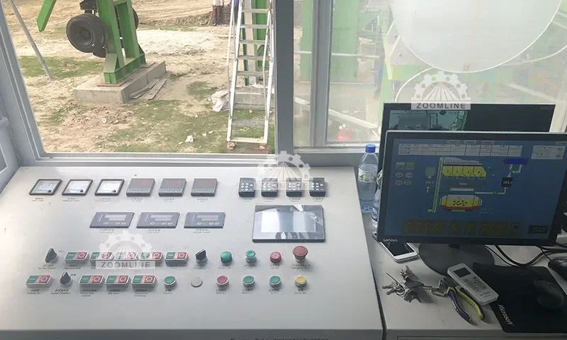
Control Cabinet and PLC (Programmable Logic Controller): This serves as the “brain” of the electrical control system. The PLC, as the core control unit, stores pre-set production programs. It regulates all equipment operations by receiving various signals and issuing commands. The control cabinet provides protection and a mounting platform for the PLC and other electrical components, ensuring circuit stability.
Sensors and Actuators: These form the system’s “sensory nerves” and “motor organs.” Sensors collect critical production data such as temperature, weight, material level, and rotational speed (e.g., asphalt temperature sensors, aggregate weighing sensors), converting this data into electrical signals transmitted to the PLC. Actuators (e.g., solenoid valves, variable frequency drives, motors) receive PLC commands to execute specific actions like start/stop, speed adjustment, and switching.
Power Distribution Unit: Including components like circuit breakers, contactors, and fuses, this serves as the system’s “power hub.” It stabilizes and distributes external power to all electrical devices while providing overload and short-circuit protection.
Human-Machine Interface (HMI): Also known as the control panel or touchscreen, this serves as the “window for human-system communication.” Operators use the HMI to configure parameters and initiate programs, while the system displays operational status, fault codes, and other information through the HMI, facilitating real-time monitoring and control.
Core Logic of System Operation
The workflow of the electrical control system can be summarized as a closed-loop process of “data acquisition—logical judgment—command execution—status feedback”: Sensors collect data such as aggregate weight and drying drum temperature → transmit it to the PLC → the PLC performs logical operations based on preset programs (e.g., determining if weight meets standards or temperature aligns with requirements) → Issues commands to actuators (e.g., halt material feeding, adjust burner intensity) → Simultaneously displays real-time operational status via HMI, triggering immediate alarms upon anomalies.
Today, digital monitoring technology enhances system intelligence—enabling managers to remotely access operational data via mobile devices or computers, proactively identifying potential faults through real-time transmission.
Tracing the Root Cause: 7 Common Causes of Electronic Control System Failures
Electronic control system failures are rarely random occurrences; they typically result from the combined effect of one or multiple factors. Identifying common causes provides direction for precise troubleshooting:
Power Supply System Issues
This is the most fundamental yet often overlooked source of failure. Problems such as excessive grid voltage fluctuations (e.g., voltage sags during peak hours), poor grounding (leading to static buildup that causes component breakdown), and short circuits (e.g., from aged or damaged cables) can directly prevent core components like PLCs and sensors from functioning properly.
Component Aging or Physical Damage
The harsh operating environment of asphalt mixing plants subjects electrical components to prolonged high-load operation, accelerating aging or damage: Oxidation of relay contacts causes poor connectivity, frequent fuse blowouts due to overloads, and solder joint detachment on circuit boards from temperature fluctuations—all potential triggers for system failures.
Sensor Malfunctions
Sensors serve as the “data source.” Their failure directly causes PLCs to receive erroneous signals, triggering control chaos. Common issues include: sensors covered in dust (e.g., aggregate level sensors accumulating ash) leading to inaccurate data, vibration causing sensor wiring to loosen, and sensor components failing in high-temperature environments.
Software and Programming Issues
Though less obvious, PLC program or HMI software failures pose significant risks. Causes may include: conflicting program logic (e.g., manual operations conflicting with automatic program commands), program loss (due to power outages or memory chip failures), compatibility issues from outdated software versions, or data transmission interruptions caused by communication line failures between PLC and HMI.
Harsh Environmental Impacts
The high-temperature, high-humidity, and high-dust conditions in asphalt mixing plants act as “silent killers” for electrical control systems: heat accelerates component aging and degrades insulation; moisture causes short circuits and metal corrosion; dust entering control cabinets settles on circuit boards and contacts, leading to poor connections or component burnout.
Human Operational Errors
Non-standard operator actions are major fault contributors: arbitrarily modifying PLC core parameters, forcibly intervening manually during automatic operation, failing to shut down systems per procedures causing program anomalies, or accidentally loosening electrical connections during equipment cleaning.
Lack of Maintenance
Failure to perform regular maintenance allows minor issues to escalate into major failures: neglecting to clean dust from control cabinets, failing to check terminal tightness, or omitting periodic sensor calibration all accelerate system aging and reduce reliability.
Step-by-Step Troubleshooting: Resolving Electrical Control System Failures in 5 Steps (Including Safety Protocols)
After a failure occurs, blind disassembly not only fails to resolve the issue but may also trigger safety incidents. Adhere to the principles of “safety first, from surface to core, and from simple to complex” to systematically troubleshoot and repair following these steps:
Step 1: Safety First, Establish a Solid Protection Foundation
The foremost requirement for addressing electrical control system faults is ensuring personnel safety. Strictly implement the Lockout/Tagout (LOTO) procedure: ① Immediately disconnect the main power supply to the mixing plant. Attach a “Under Maintenance, Do Not Operate” warning sign to the power switch and secure it with a lock. ② Verify the equipment has completely stopped with no components moving due to inertia. ③ Wear protective gear such as insulated gloves and insulated shoes to prevent electric shock. ④ If the work environment contains dust or high temperatures, implement ventilation and cooling measures first.
Step 2: Conduct a Preliminary Inspection to Pinpoint the Fault Range
Avoid immediate disassembly. First, use “visual inspection, auditory checks, and verification” to preliminarily determine the fault direction: ① Examine the HMI interface and record fault codes (e.g., “Sensor Communication Failure,” “Voltage Abnormality”), as these codes provide the most direct clues to the fault; ② Observe indicator lights inside the control cabinet, such as whether the power light is on or fault lights are flashing. Check if fuses are blown and inspect wiring for obvious looseness or burn marks; ③ Listen to operational sounds (if power is still on), such as unusual motor noises or abnormal contactor engagement sounds, to preliminarily assess actuator functionality.
Step 3: Precise Testing to Pinpoint the Fault Source
Based on preliminary findings, employ specialized tools for targeted diagnostics to pinpoint specific faults: ① Circuit Testing: Use a multimeter to measure voltage and current at the power distribution unit to verify stable power supply; employ an insulation tester to assess circuit insulation integrity and identify short circuits or ground faults. ② Component Testing: Conduct isolated tests on sensors—e.g., calibrate load cells with standard weights to verify accurate output signals. Disassemble suspected faulty relays or contactors and use a multimeter to measure contact continuity. ③ Program and Communication Testing: Connect to the device via PLC programming software to verify program logic integrity and identify command conflicts. Inspect communication lines between the PLC, HMI, and sensors to ensure secure, undamaged wiring; reseat communication connectors if necessary.
Step 4: Targeted Troubleshooting for Efficient Resolution
After identifying the fault location, implement specific solutions based on the issue type: ① Component Replacement: Immediately replace burnt-out fuses, oxidized relays, or failed sensors with identical model and specification parts (use original manufacturer components for compatibility assurance); ② Circuit Repair: Tighten loose terminals with a screwdriver; insulate or replace damaged cables; sand and reconnect corroded joints; ③ Software & Parameter Repair: Import backed-up PLC programs if lost; reset HMI parameters to production standards if incorrect; contact the manufacturer to upgrade outdated software to the latest version; ④ Sensor Calibration: Calibrate inaccurate sensors using specialized equipment to ensure collected data (temperature, weight, etc.) meets precision requirements.
Step 5: System Reset and Testing Validation
After repairs, do not immediately resume full-load production. Conduct testing in the following steps: ① Remove safety locks, turn on the main power supply, and observe whether control cabinet indicator lights and HMI interface start normally without fault alarms; ② Start the system in “idle” mode and run for 30 minutes. Check whether all processes (mixing, heating, feeding, etc.) operate in coordination and whether sensor data remains stable. ③ Conduct small-batch trial production to simulate actual operating conditions. Verify that product quality (e.g., asphalt mixture temperature, mix ratio) meets standards. Only resume normal production after confirming no system abnormalities.
Prevention is Better Than Cure: Six Key Measures to Reduce Failure Rates
Compared to reactive repairs after failures, proactive prevention more effectively ensures system stability and lowers operational costs. We recommend establishing the following preventive mechanisms:
Develop a Regular Maintenance Schedule
Perform a comprehensive monthly cleaning of control cabinets to remove dust and debris.
Conduct quarterly inspections of terminal tightness, relay contact status, and sensor calibration. Conduct performance tests on circuit breakers and contactors in power distribution units every six months, replacing aged components promptly.
Optimize Operating Environment
Install dust-proof, moisture-proof, and heat-dissipating devices (e.g., dust filters, axial fans, dehumidifiers) on control cabinets to prevent high temperatures, humidity, and dust from corroding electrical components; add protective covers to sensors to minimize material residue and vibration impacts.
Ensure stable power supply
Equip the mixing plant with voltage stabilizers and surge protectors to withstand grid voltage fluctuations and lightning strikes; regularly inspect the grounding system to ensure grounding resistance meets standards (generally ≤4Ω).
Strengthen software management
Regularly back up PLC programs and HMI parameters, storing them in secure locations; promptly monitor manufacturer software update notifications, upgrading as needed to patch program vulnerabilities; prohibit unauthorized personnel from modifying core programs or parameters.
Enhance Personnel Training
Provide systematic training for operators to master standardized procedures (e.g., startup/shutdown sequences), common fault identification methods, and emergency response measures; implement an “Operational Log” system to document daily system status and anomalies.
Stock Emergency Spare Parts
Pre-purchase commonly used consumables such as fuses, relays, sensors, and cable connectors, storing them in a dry, well-ventilated spare parts warehouse. Simultaneously back up PLC programs and equipment manuals to ensure rapid response during failures.
Professional Support: Contact the Manufacturer Immediately in These Situations
Not all malfunctions are suitable for on-site self-resolution. Contact the equipment manufacturer or a professional electrical engineer promptly when encountering the following scenarios to prevent escalating issues due to incorrect handling:
Complex logic errors in PLC programs that cannot be resolved by simply importing a backup;
Damage to high-end components such as burned-out core circuit boards or PLC host failures;
Malfunctions in precision components like sensors or actuators where specialized calibration equipment is unavailable;
Frequent, irregular system failures where root cause cannot be identified through self-troubleshooting.
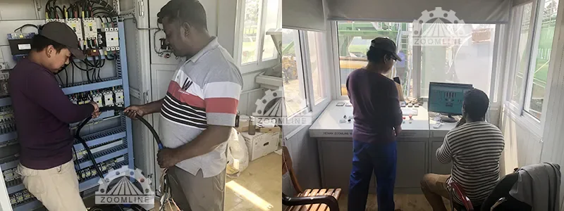
Today, most leading asphalt mixing plant manufacturers offer remote monitoring and technical support services. By connecting equipment to their network, manufacturer engineers can view real-time system data, diagnose faults remotely, and even resolve certain software issues online—significantly reducing downtime.
Conclusion: Safeguarding Production Continuity Through Proactive Maintenance
The reliability of an asphalt mixing plant’s electrical control system directly determines production “continuity” and “safety.” While a systematic troubleshooting process helps resolve issues swiftly, it is more crucial to adopt a “prevention-first, repair-second” philosophy—reducing failure rates at the source through regular maintenance, standardized operations, and environmental optimization.
Remember: Every meticulous inspection and every standardized operation safeguards the stable operation of your mixing plant. Should you encounter challenges in electrical system maintenance or fault resolution, consult professional equipment service providers anytime. Let expertise amplify your production efficiency.