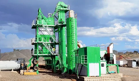


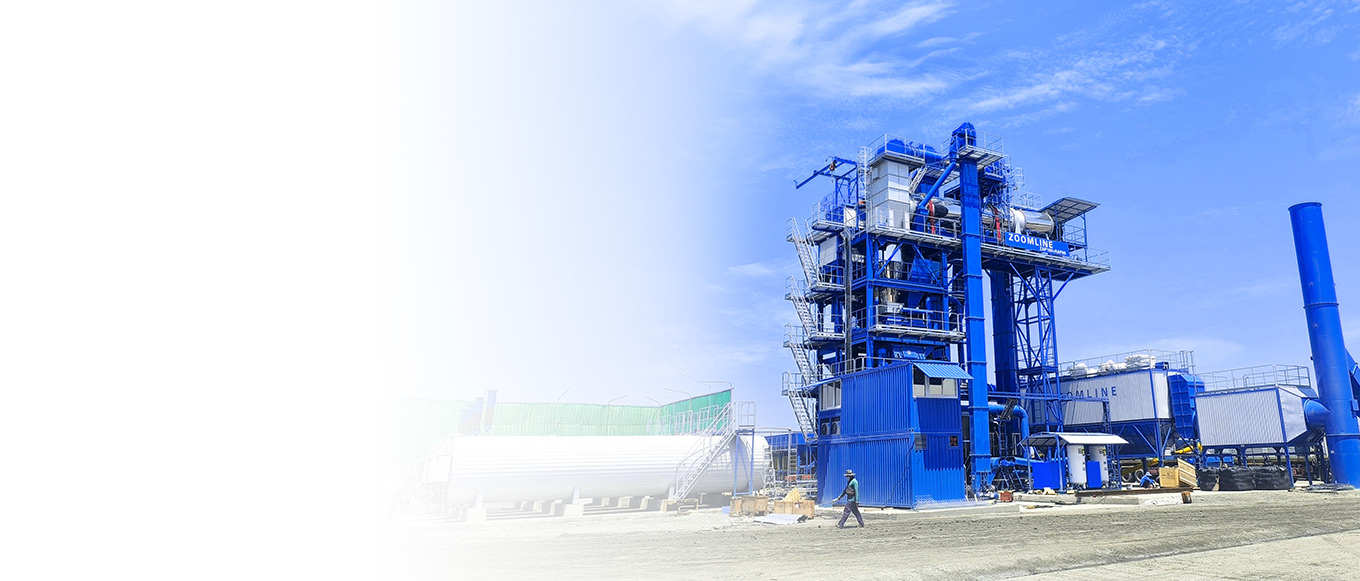


How to Control Flue Gas Emissions from Asphalt Mixing Plants
Asphalt mixing plants, serving as core equipment in road construction, face significant challenges in flue gas emissions during production—a critical bottleneck in the industry’s green transformation. Industry monitoring data indicates that an asphalt mixing plant with an annual production capacity of 300,000 tons, if lacking effective control measures, can emit an average of 8-12 tons of particulate matter and 3-5 tons of volatile organic compounds (VOCs) annually. The flue gas contains substances like polycyclic aromatic hydrocarbons (PAHs) with strong carcinogenic properties. These emissions not only cause a 15%-20% increase in surrounding PM₂. With the strict enforcement of policies like the “Emission Standard for Air Pollutants from Asphalt Concrete Mixing Plants” (GB 37822-2019), establishing a “full-process, multi-dimensional, high-precision” flue gas control system has become an imperative requirement for the compliant operation and sustainable development of asphalt mixing plants. Based on engineering practice and technical parameters, this paper systematically deconstructs the specific pathways and implementation details of fume control at asphalt mixing plants from four dimensions: emission characteristics, technical systems, process optimization, and operational maintenance assurance.
Sources and Pollutant Characteristics of Asphalt Mixing Plant Flue Gas
Emissions from asphalt mixing plants exhibit characteristics of “concentrated point sources, diffuse area sources, and complex composition.” Identifying emission origins and pollutant properties is essential for targeted control measures.
Core Emission Source Identification and Emission Intensity
Based on emission patterns and concentration variations, emission sources can be categorized into two main types: process emissions and fugitive emissions. The emission intensity and pollutant contribution differ significantly between these sources:
Process Emissions (70%-80% of Total Emissions)
E1 Stack (Primary Emission Outlet): The dryer burner constitutes the primary process emission source. Fuel combustion generates over 90% of the plant’s total NOₓ, CO, and SO₂ emissions, while the aggregate drying process contributes 85% of particulate matter (primarily PM₁₀). Taking a downflow dryer using heavy fuel oil (No. 6 residual fuel oil) as an example: at a production rate of 120 tons/hour and aggregate moisture content of 10%, stack outlet particulate matter concentrations can reach 800-1200 mg/m³, with NOₓ concentrations of 300–400 mg/m³, far exceeding national standards (PM₁₀ ≤ 20 mg/m³, NOₓ ≤ 150 mg/m³). Mixing Tower: During asphalt mixing with hot aggregate, light components in asphalt (e.g., alkanes, aromatics) are thermally stripped, generating VOCs and asphalt fumes. Emissions amount to approximately 0.3-0.5 kg per ton of asphalt. Characteristic pollutants like benzene, toluene, and xylene constitute 35%-45% of total VOCs and emit a strong, pungent odor.
Fugitive emission sources (accounting for 20%-30% of total emissions)
E2 Baghouse Dust Collector / Filler Bin: When pneumatic feeding is used in the filler bin, dust dispersion concentrations can reach 50-100 mg/m³ if sealing is inadequate. Particularly in environments with wind speeds exceeding 3 m/s, dust dispersion can extend up to 50-80 meters. If the filter bag damage rate in the baghouse exceeds 5%, the outlet dust concentration will surge from below 20 mg/m³ to over 100 mg/m³.
E3 Asphalt Tank / Vent Pipe: During heating (160-180°C), asphalt fumes naturally vent through the pipe at concentrations of 20-50 mg/m³, containing approximately 0.05-0.1 mg/m³ of PAHs, posing a potential soil contamination risk.
E4 Asphalt Loading Point: When finished asphalt is loaded from silos into transport trucks, temperature fluctuations (150-170°C) and pressure differentials cause instantaneous VOC emissions. Each loading operation emits approximately 0.02-0.03 kg. If uncollected, odors can spread within a 100-meter radius.
Pollutant Composition and Physicochemical Properties
Pollutants in asphalt mixing plant exhaust can be categorized into three types, with their physicochemical properties directly determining control technology selection:
Particulate Matter: Size distribution ranges from 0.1-100μm, with PM₁₀ (≤10μm) accounting for 60%-70% and PM ₂ . ₅ (≤2.5μm) comprising 20%-30%. These particles adsorb organic pollutants from asphalt fumes, forming “composite pollutant particles.” They exhibit slow settling velocities (PM₂.₅ settling velocity: ~0.001-0.01 m/s), readily penetrate human alveoli, and increase the risk of pneumoconiosis with prolonged exposure.
Gaseous pollutants: These include NOₓ (primarily NO, accounting for 70%-80%), CO, and SO₂. Among these, NOₓ is categorized into thermal NOₓ (comprising over 80%, formed rapidly at combustion temperatures >1300°C) and fuel-derived NOₓ (less than 20%, converted from
nitrogen in fuels). SO₂ generation exhibits a linear relationship with fuel sulfur content. For instance, No. 6 residual fuel oil with 2%-3% sulfur yields SO₂ emissions of 800-1200 mg/m³, whereas natural gas (<0.001% sulfur) produces negligible SO₂ emissions.
Organic pollutants: Primarily VOCs and PAHs. Key VOC components include benzene (5%- 8%), toluene (10%-15%), xylene (8%-12%), naphthalene (15%-20%). Among these, benzene is a Group 1 carcinogen, and ambient concentrations exceeding 0.1 mg/m³ pose health risks to humans. Among PAHs, benzo[a]pyrene (BaP) exhibits the strongest carcinogenicity. Its concentration in asphalt fumes is approximately 0.005–0.01 mg/m³, necessitating strict control.
Core Technical Framework for Fume Control
Asphalt mixing plant fume control requires a three-tiered technical system: “source reduction – end-of-pipe purification – fugitive collection.” Each stage must select appropriate technical solutions and define key parameters based on pollutant characteristics and production scenarios.
Source Reduction: Minimizing Pollutant Generation at the Emission Source
Source reduction is fundamental to lowering treatment costs and enhancing control efficiency. Optimizing combustion systems, improving heating methods, and regulating drying processes can reduce pollutant generation by 30%-50%.
Combustion System Upgrades and Parameter Optimization The burner serves as the “core source” of process emissions, with its type and operating parameters directly determining pollutant generation efficiency:
Burner Selection: Compared to traditional induced draft burners, forced draft burners use fans to deliver combustion air, improving air-fuel ratio control accuracy to ±5% (vs. ±15% for induced draft). This boosts fuel utilization by 15%-20%, reduces CO emissions by 25%-30%, and lowers VOC emissions by 20%-25%. For example, at a 120-ton/hour mixing plant, adopting forced-draft burners reduced annual fuel consumption from 1,800 tons (heavy oil) to 1,500 tons while lowering CO emissions from 150 mg/m³ to below 100 mg/m³.
Microprocessor Closed-Loop Control: The combustion system equipped with a PLC (Programmable Logic Controller) continuously monitors aggregate temperature at the dryer outlet (via infrared sensor, accuracy ±2°C), aggregate moisture content (microwave sensor, accuracy ±0.5%), and flue gas oxygen content ( , zirconia sensor, accuracy ±0.1%). It dynamically adjusts fuel supply and airflow accordingly. When aggregate moisture content decreases from 10% to 5%, the system automatically reduces fuel supply by 20%-25% to prevent NOₓ increases caused by “overburning.” When oxygen content falls below 18%, air volume is automatically increased to prevent incomplete combustion that generates CO and VOCs.
Combustion Temperature Control: Thermal NOₓ generation is negligible below 1300°C, thus burner flame temperature must be maintained between 1200-1250°C. By adjusting the burner nozzle angle (30°-45°) and flame length (1.5-2.0 meters), direct flame contact with the dryer cylinder inner wall (temperature <800 °C) is avoided. Simultaneously, “staged combustion” technology divides combustion air into primary air (60%-70%) and secondary air (30%-40%). Secondary air is introduced at the flame tail to reduce local combustion temperatures, lowering NOₓ emissions by 30%-40%.
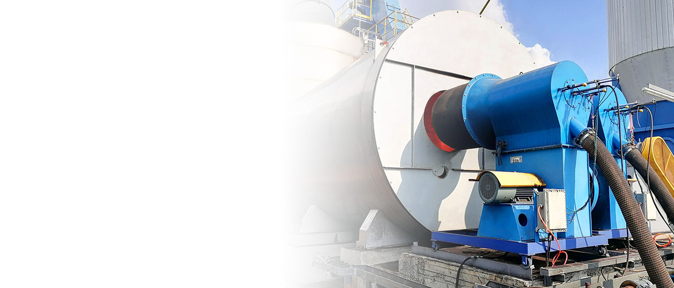
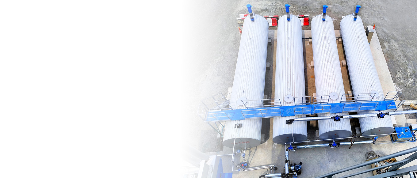
Asphalt Heating Innovation Traditional thermal oil furnace heating for asphalt suffers from “high emissions and significant heat loss,” whereas the electric heating asphalt tank system achieves “zero combustion emissions”:
Electrical Heating System Design: Stainless steel heating tubes (316L grade, temperature resistance exceeding 250°C) are employed. Heating power is configured based on tank capacity—e.g., a 50m³ asphalt tank utilizes 60-80kW heating tubes. With a heating rate of 5- 8°C/hour, asphalt temperature is stably maintained between 160-180°C (±3°C fluctuation), preventing excessive asphalt fumes caused by localized overheating. hours, maintaining stable asphalt temperatures between 160-180°C (±3°C fluctuation) to prevent excessive asphalt fumes caused by localized overheating.
Enhanced insulation design: Tank walls feature 200mm thick rock wool insulation (thermal conductivity ≤0.04W/(m·K)), externally clad with 0.5mm thick color-coated steel plates. Heat loss rate reduced to below 5% (traditional tanks use 50-100mm rock wool with 15%-20% heat loss). Based on 300 operating days per year, the electrically heated tank saves 20%-25% energy compared to traditional thermal oil furnace tanks while eliminating SO₂ (approx. 0.5 tons/year) and CO (approx. 0.2 tons/year) emissions from thermal oil furnaces.
Controlling the operating state of the drying cylinder during aggregate drying directly impacts particulate matter and VOCs generation. Optimizing the “material curtain” and rotational speed enhances drying efficiency while reducing emissions:
Variable Frequency Drive (VFD) Technology: The drying cylinder is equipped with a 15-30kW VFD motor, allowing speed adjustment within the 3-6 r/min range. At a production load of 80 tons/hour (low load), the speed is set to 3-4 r/min, extending aggregate residence time within the cylinder (15-20 minutes) to ensure thorough drying. When load increases to 120 tons/hour (high load), speed is adjusted to 5-6 r/min to maintain uniform material curtain thickness (50-80 mm). By optimizing rotational speed, aggregate moisture content can be stably controlled within 0.5%-1.0% (design requirement), preventing secondary drying (increased fuel consumption and emissions) due to excessive moisture or aggregate overheating (releasing additional dust) caused by insufficient moisture.
Optimized Material Curtain Design: Install “stepped board” inside the drying cylinder at an angle of 30°-45° with spacing of 200-300mm to ensure uniform lifting of aggregates forming a “material curtain.” When material curtain uniformity exceeds 90%, burner radiation heat utilization increases by 15%-20%, drying time is reduced by 2-3 minutes, fuel consumption decreases by 8%-12%, and NOₓ and CO emissions are indirectly reduced.
End-of-pipe purification: Efficient removal of generated pollutants
End-of-pipe purification is a critical step in ensuring emissions meet standards. It requires selecting appropriate technologies for particulate matter, organic pollutants, and gaseous pollutants, while defining equipment parameters and operational requirements.
Particulate Matter Control Technology Based on particle size and flue gas temperature, different types of dust removal equipment are selected to form a “pre-treatment – fine treatment” combined process:
Cyclone Dust Collector (Pre-treatment): Suitable for ambient temperature applications (<80° C) such as cold feeders and belt conveyors, and large-particle dust (>5μm). Equipment diameter is designed based on airflow volume; for example, a 10,000m³/h airflow requires a 1.2-1.5m diameter unit with an inlet velocity of 18-22m/s. Centrifugal force achieves 85%-90% removal efficiency for large particles. Taking a cold material machine as an example, dust emission concentrations can reach 200-300 mg/m³ without a cyclone dust collector. Installation reduces this to 30-50 mg/m³, alleviating the load on subsequent fine treatment processes.
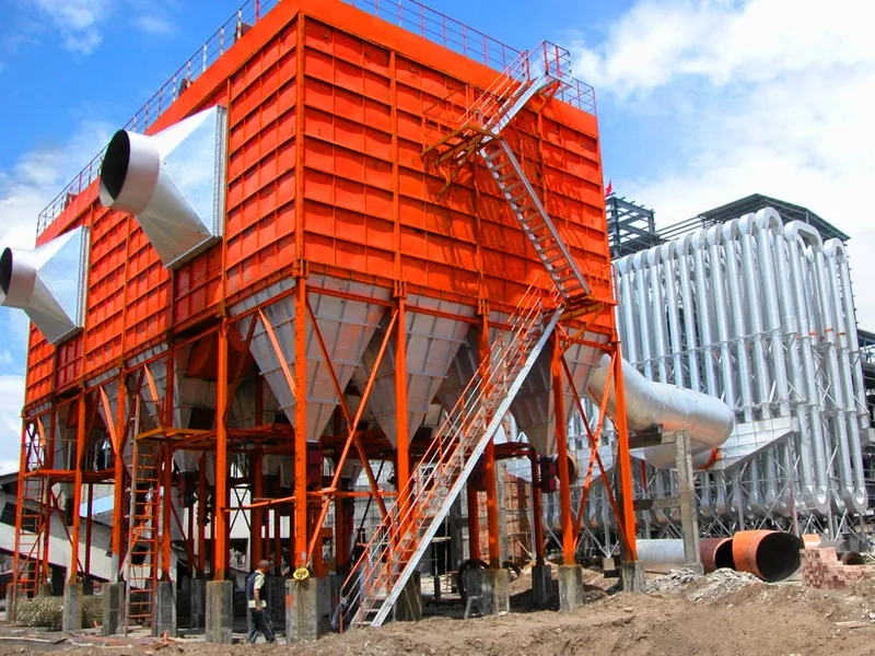
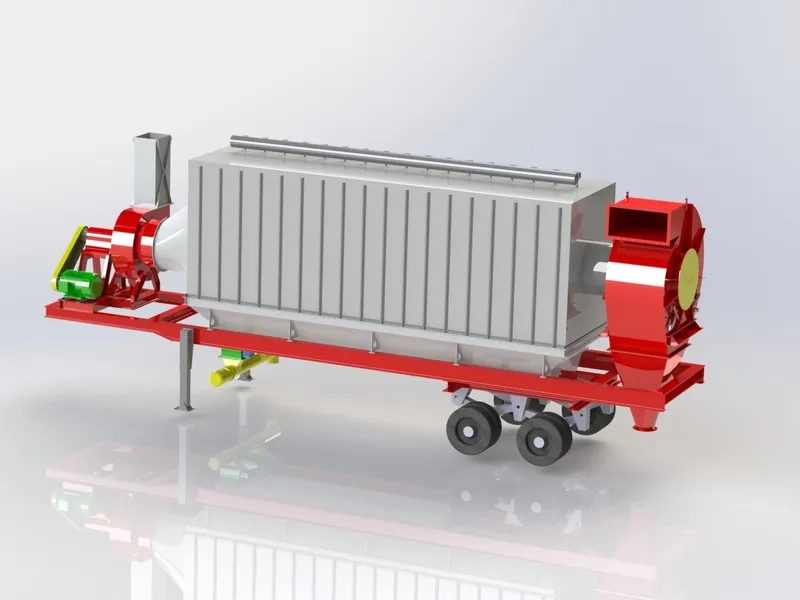
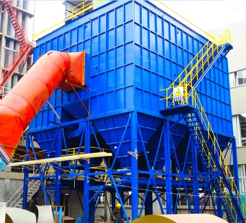
High-Temperature Baghouse Dust Collector (Fine Treatment): Serves as the “core equipment” for particulate control in mixing plants, designed to handle high-temperature (180-250°C) and high-humidity (60%-80% relative humidity) flue gas conditions:
Filter Bag Selection: Utilizes Nomex (aramid) filter bags with a temperature resistance of 200- 250°C and a short-term resistance of 280°C. Filtration precision reaches 0.1μm, achieving 99.9% removal efficiency for PM₂.₅. Filter bag dimensions are designed based on filtration area. For example, with an airflow volume of 50,000 m³/h and a filtration velocity of 1.0-1.2 m/min, 800-99 filter bags are required. Post-treatment non-methane total hydrocarbon concentration can be reduced to below 1.0mg/m³, meeting the newly added VOCs limit standards in JT/T 1539-2025 “Technical Requirements for Green Production of Asphalt Mixing Plants.” The equipment operates with low energy consumption (only 15-20 kW power consumption at a treatment air volume of 10,000 m³/h) and produces no secondary pollution, making it suitable for long-term continuous operation.
Low-Temperature Plasma Method: Targeting hard-to-degrade macromolecular VOCs (e.g., benzo[a]pyrene), this method employs a high-voltage pulse power supply (10-30kV, 50- 100Hz) to generate high-energy electrons (10-20eV). These electrons collide with VOC molecules, causing them to crack into free radicals while simultaneously producing ozone (O₃) to oxidize the free radicals. The final conversion products are CO₂ and H₂O. The equipment employs a “honeycomb electrode” structure, handling airflow rates of 5000-20000m³/h. It achieves over 90% removal efficiency for benzene and toluene, making it particularly suitable for advanced treatment of PAHs in mixed tower effluents. During operation, gas humidity must be controlled (relative humidity < 70%) to prevent electrode condensation from affecting discharge efficiency. Dust accumulation on electrode surfaces requires periodic cleaning (every 1-2 months).
NOₓ and SO₂ Control Technologies
Addressing the characteristics of gaseous pollutants requires a combined approach of “source substitution + end-of-pipe conversion”:
SO₂ Control: The core lies in controlling fuel sulfur content, prioritizing low-sulfur fuels. For instance, replacing No. 6 residual fuel oil (2%-3% sulfur content) with natural gas (<0.001% sulfur) reduces SO₂ emissions from 800-1200 mg/m³ to near-zero levels. Using distillate oils No. 1-2 (<0.5% sulfur) SO₂ emissions can be controlled at 100-150 mg/m³. When high-sulfur fuels are unavoidable, wet desulfurization systems must be employed, such as the limestone method – Gypsum method: Limestone (CaCO₃) slurry (10%-15% concentration) is sprayed into the desulfurization tower, reacting with SO₂ to form calcium sulfite (CaSO₃). Oxidation fans
then introduce air to generate gypsum (CaSO₄・2H₂O), achieving desulfurization efficiency exceeding 90% with post-treatment SO₂ emissions ≤50mg/m³.
NOₓ Control: Beyond controlling combustion temperatures at the source, end-of-pipe denitrification technologies are critical. Selective Catalytic Reduction (SCR) technology is well- established in asphalt mixing plants. It operates by using ammonia water or urea as a reductant, which reacts with NOₓ at temperatures between 300-400°C under the influence of a catalyst (e.g., V₂O₅-WO₃/TiO₂) to form N₂ and H₂O. This process achieves denitrification efficiencies of 80%-90%. Taking a Jiangxi mixing plant with an annual asphalt concrete production capacity of 300,000 tons as an example, installing an SCR denitrification facility after the baghouse dust collector, combined with secondary alkali solution scrubbing, reduced NOₓ emissions from 300-400 mg/m³ to below 50 mg/m³, meeting stringent local emission standards. During SCR system operation, the reductant injection volume must be controlled (ammonia-to-nitrogen ratio of 1.0-1.2) to prevent secondary pollution caused by excessive ammonia escape (concentration < 5 mg/m³). Catalyst activity should be tested every 6-12 months, with regeneration or replacement required when activity drops below 70% of the initial value.
Fugitive Emission Collection: Blocking Diffusion Pathways
Fugitive emissions exhibit characteristics of “low concentration and wide dispersion.” Control centers on “sealing + negative pressure collection + regional management” to ensure a collection efficiency exceeding 90%.
Equipment and Area Sealing Design Differentiated sealing measures are applied to various fugitive emission points:
Cold Feeder and Belt Conveyor: Install fully enclosed color-coated steel enclosures (0.5mm thickness, internally lined with 50mm rock wool insulation). Seal gaps between enclosure and equipment with rubber gaskets, bolted at interfaces to prevent dust leakage. Cold material feeder inlet: Equipped with a “dust-proof baffle” that automatically opens during loader unloading and closes afterward to minimize instantaneous dust generation.
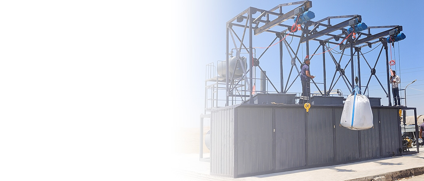
Filler and finished product silos: Install “rolling seal doors” at feed openings. These doors roll with the movement of material transport vehicles, maintaining a constant seal. Equip silo tops
with “pulse-jet baghouse dust collectors” (filtration area ≥50m²). These capture dust generated during pneumatic feeding, ensuring negative pressure (-20 to -50Pa) inside silos to prevent dust overflow from silo openings. A Beijing mixing plant reduced fugitive particulate emissions from 10 mg/m³ to below 5 mg/m³ by installing cyclone dust collectors
+ spray systems on hot aggregate silos and maintaining daily cleaning logs, meeting JT/T 1539-2025 standards.
Asphalt Tanks and Loading Points: Install “condensation recovery devices” on tank vent pipes to recondense and recirculate escaping asphalt fumes. Seal tank openings with flanges, replacing gaskets every 3-6 months. Equip loading points with adjustable negative-pressure hoods (1.5-2.0 m diameter), adjustable to truck height with a 30-50cm clearance from the loading port. An exhaust fan (airflow 2000-3000m³/h) collects fugitive VOCs into an activated carbon adsorption tower, achieving over 95% collection efficiency.
Negative Pressure Extraction Collection System Optimizing the negative pressure system design requires ensuring “pressure equilibrium and flow matching”:
Fan Selection and Ductwork Design: The main exhaust fan employs a variable-frequency centrifugal blower. Airflow is designed based on total fume volume (e.g., a 120-ton/hour mixing plant requires 60,000-80,000 m³/h total airflow) with a pressure of 1500-2000 Pa. It interfaces with PLC-controlled valves at each collection point. When a hood at any node opens, the fan speed automatically increases to maintain negative pressure. The ductwork utilizes circular galvanized steel pipes (diameter 300-500 mm). Duct velocity is controlled at 12-18 m/s to prevent dust deposition and blockage caused by low flow rates. Elbow curvature radius ≥ 3 times the pipe diameter to minimize airflow resistance.
Pressure Monitoring and Regulation: Pressure sensors (±10Pa accuracy) are installed at critical nodes like mixing towers and aggregate bins to monitor negative pressure in real time. When tower pressure drops below -50Pa, the system automatically opens fan inlet valves to increase airflow. During pressure fluctuations caused by simultaneous activation at multiple nodes, valve openings are adjusted to redistribute airflow, ensuring stable negative pressure within design parameters at every collection point.
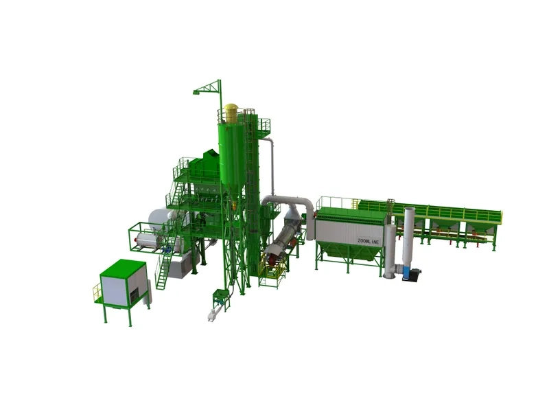
Fully Enclosed Conveying System: The entire conveying path from aggregate arrival to finished product dispatch employs an enclosed design:
Aggregate Conveyance: A closed belt conveyor gallery connects the cold aggregate feeder to the drying drum. From the drying drum to the screening machine and hot aggregate silo, closed elevators and chutes are employed. The chute inner walls are lined with wear-resistant ceramic plates (10-15mm thick) to minimize dust generated by material impact.
Finished Product Conveyance: A closed screw conveyor or bucket elevator connects the mixing tower to the finished product silo. A telescopic enclosed discharge pipe extends from the silo to the loading point, with the discharge pipe tip positioned ≤30cm above the truck bed floor to minimize dust generation during material drop. This fully enclosed process reduces fugitive dust emissions by over 60% and controls boundary dust concentration below 0.5mg/m³.
Impact of Process Design and Operational Parameter Optimization
The rationality of process design and the precision of operating parameters directly determine the stability and economic efficiency of the flue gas control system. These aspects require comprehensive planning during the engineering design phase and dynamic adjustment during the operational phase.
Selection of Dryer Type and Flow Pattern
The flow pattern within the drying cylinder directly impacts pollutant generation and treatment difficulty. Selection must balance environmental requirements and production needs:
Counterflow Dryer: Aggregate and hot flue gas flow in opposite directions. Hot flue gas enters at the dryer tail, contacting freshly introduced wet aggregate and gradually cooling (tail gas temperature: 120-150°C). Aggregate reaches peak temperature (180-200°C) near the burner before entering the mixing tower. This flow pattern enables asphalt-aggregate mixing in a “non-high-temperature zone,” reducing VOC emissions by 30%-40% compared to co-current systems. It is particularly suitable for regions with high RAP blending rates (30%- 50%) or stringent environmental regulations. A counterflow dryer mixing plant maintained VOC emission concentrations below 30 mg/m³ even with 40% RAP content, eliminating the need for additional deep treatment equipment.
Downflow Dryer: Aggregate and hot flue gas flow in the same direction. Hot flue gas enters at the head and moves synchronously with the aggregate. Flue gas temperature at the head reaches 800-1000°C. Aggregate reaches its peak temperature at the tail before entering the mixing tower. This flow pattern offers high drying efficiency (10%-15% higher than counter- current drying) but features elevated temperatures in the mixing zone. Particularly when blending RAP, significant release of light components from old asphalt can result in VOC emissions reaching 1.5-2.0 times those of counter-current drying. Therefore, downflow dryers require enhanced end-of-pipe VOC purification, such as adopting the “combustion + UV photocatalysis” process ( ) to reduce VOC emission concentrations below 50 mg/m³.
Precise Control of Combustion and Drying Parameters
Optimizing operating parameters must focus on balancing efficiency and emissions. Core parameters include:
Combustion Temperature and Oxygen Content: The burner flame temperature must be strictly controlled between 1200-1250°C, monitored in real-time via infrared thermometers. When temperatures exceed 1300°C, fuel supply is automatically reduced or secondary airflow
increased. Flue gas oxygen content must be maintained between 18%–20%. Oxygen levels below 18% cause incomplete combustion (elevated CO), while levels exceeding 20% increase NOₓ formation and heat loss. By optimizing oxygen content parameters, a mixing plant reduced CO emissions from 150 mg/m³ to 80 mg/m³ while lowering fuel consumption by 5%. Dryer Drum Speed and Fill Rate: Speed should match production load. At low loads (60-80 tons/hour), maintain 3-4 rpm; at high loads (100-120 tons/hour), maintain 5-6 rpm. Aggregate filling rate is controlled between 10%-15%. Excessive filling causes overly thick material curtains (>100mm), leading to inadequate heat exchange, while insufficient filling results in dust dispersion (increased particulate emissions). By adjusting the filling rate, particulate emissions at one mixing plant decreased from 30mg/m³ to 15mg/m³.
Asphalt Temperature and Mixing Time: Maintain asphalt temperature at 160-180°C with ± 3°C fluctuation to prevent localized overheating and excessive asphalt fumes. Control mixing time in the mixing tower at 30-45 seconds to ensure thorough asphalt coating of aggregates, reducing volatilization of unbound asphalt (capable of lowering VOC emissions by 10%-15%).
Adaptive Control of RAP Blending Ratio
The incorporation of Reclaimed Asphalt Pavement (RAP) increases VOC emissions and requires adjustment based on dryer type and processing technology:
Counterflow dryer: Due to lower temperatures in the mixing zone, higher RAP blending rates (30%-50%) can be accommodated. When increasing the blend ratio from 30% to 50%, reduce the aggregate temperature at the dryer outlet by 5-10°C (to 170-180°C) while extending the mixing time by 5-10 seconds. This ensures thorough activation of the recycled asphalt and minimizes the release of light components. At a counterflow mixing plant blending 50% RAP, VOC emissions remained stable at 25-30 mg/m³ through parameter adjustments.
Downflow dryer: Recommended RAP blending rate is 10%-30%. When exceeding 30%, install an “asphalt fume pretreatment system”—such as adding a condenser at the mixing tower outlet to recover 60%-70% of asphalt fumes before UV photocatalytic treatment—to ensure VOC emissions meet standards. At a certain downflow mixing plant, when blending 30% RAP, this integrated process reduced VOC emissions from 80 mg/m³ to below 40 mg/m³.
Monitoring and Maintenance: Ensuring Long-Term Stable Operation of Control Systems
For fume control equipment, “30% depends on selection, 70% on operation and maintenance.” A closed-loop management system of “monitoring – maintenance – optimization” must be established to ensure long-term, efficient equipment operation.
Application of Comprehensive Emission Monitoring Technology
Monitoring is central to evaluating control effectiveness and identifying issues, requiring a combination of online monitoring and manual testing:
C ontinuous Emission Monitoring System (CEMS): Install CEMS at the stack (main emission point) to continuously monitor particulate matter, NOₓ, SO₂, CO, and other parameters such as flue gas flow rate, temperature, and humidity. Monitoring data must be uploaded to the environmental protection department’s regulatory platform every hour, with a data validity rate of ≥90%. CEMS equipment must comply with HJ/T 76 standards. Particulate matter measurement employs beta ray absorption (accuracy ±5%), while gaseous pollutants use infrared absorption (accuracy ±2%). Calibration is performed every three months to ensure data accuracy.
Fugitive Emission Monitoring: Set up 4-6 monitoring points at the upwind and downwind sides of the plant boundary. Use portable dust detectors (measuring range 0.01-100 mg/m³, accuracy ±0.01 mg/m³) and VOCs detectors (measuring range 0.01-100 mg/m³, accuracy
±0.01 mg/m³). Conduct monitoring once per quarter, Each monitoring session lasts 2-3 days, ensuring particulate matter concentration at the boundary ≤5 mg/m³ and non-methane total hydrocarbon concentration ≤1.0 mg/m³ (as per JT/T 1539-2025 standard requirements). Equipment Operation Status Monitoring: Install differential pressure sensors (measuring range 0-5000 Pa, accuracy ±10 Pa) at the inlet and outlet of the baghouse dust collector. When differential pressure exceeds 2000 Pa, indicate filter bag clogging requiring enhanced cleaning. Install NOₓ sensors at the inlet and outlet of the SCR denitrification system. When denitrification efficiency falls below 70%, indicate decreased catalyst activity requiring replacement. Install air velocity sensors in the negative pressure collection system ductwork. When air velocity falls below 12 m/s, trigger an alert indicating duct blockage requiring cleaning.
Core Equipment Maintenance Strategy and Procedures
Maintenance requirements vary significantly across different equipment, necessitating tailored maintenance plans:
Baghouse Dust Collector Maintenance
Daily Maintenance: Inspect pulse cleaning system operation every 2 hours to ensure compressed air pressure remains stable at 0.5-0.7 MPa with a pulse duration of 0.1-0.2 seconds. Check hopper dust accumulation every 8 hours via level sensors. When dust exceeds 2/3 of hopper capacity, activate screw conveyor for ash discharge to prevent bridging and blockages.
Periodic Maintenance: Monthly: Open inspection doors to examine filter bag integrity using the “light leak detection method” (illuminate the interior with a strong light source while
observing for light leakage externally). Immediately replace damaged bags (damage rate must remain <5%). Clean pulse valve nozzles and blow pipes every 3 months to prevent oil residue blockage. Filter bags typically last 2-3 years; replace all bags upon expiration, prioritizing anti-adhesive, high-temperature-resistant materials like Mites coated filter media. Special Maintenance: When treating highly viscous asphalt fumes, employ “pre-coating technology” by applying a 1-2mm layer of lime powder to the filter bag surface to reduce asphalt adhesion. Reapply the pre-coating every 15-30 days.
VOC Purification Equipment Maintenance
Activated Carbon Adsorption Tower: Check the VOC concentration difference at the inlet and outlet every 1-3 months. Replace activated carbon when the difference falls below 30% of the initial value (columnar activated carbon typically lasts 3-6 months). Inspect the adsorption tower’s sealing integrity monthly; use silicone gaskets at interfaces to prevent gas bypassing. Dispose of spent activated carbon through qualified entities; do not discard it arbitrarily.
UV Photocatalytic Equipment: Clean oil and dust from UV lamp surfaces monthly to ensure
≥90% light transmittance. Replace UV lamps every 6-12 months (service life approx. 8,000- 10,000 hours). Inspect catalyst coatings quarterly; reapply TiO₂ catalyst if peeling occurs.
Low-Temperature Plasma Equipment: Clean dust from electrode surfaces every 1-2 months using compressed air (0.3-0.5 MPa pressure). Inspect high-voltage power supply insulation every 6 months to prevent moisture-induced short circuits. Regularly drain condensate from the equipment base to prevent electrode corrosion.
SCR DeNOx System Maintenance
Daily Maintenance: Check the reductant (ammonia water/urea) storage tank level every 4 hours to ensure it remains ≥1/3 full. Simultaneously monitor the reductant injection pump pressure (maintain stable at 0.3-0.5MPa). Check the catalyst reactor temperature every 8 hours to ensure it remains within the active range of 300-400°C.
Periodic Maintenance: Test catalyst activity every 6 months via denitrification efficiency assessment. Regenerate with “high-temperature purging” (injecting 400-450°C hot air) when activity declines. Clean accumulated dust and oil residue inside reactors every 12 months to prevent catalyst channel blockage. Catalyst lifespan is approximately 3-5 years; replace upon expiration.
Negative Pressure Collection System Maintenance
Fan Maintenance: Clean dust from fan impellers monthly using a soft-bristle brush to prevent imbalance-induced vibration. Lubricate bearings every 3 months with lithium-based grease (filling 1/2–2/3 of bearing volume). Inspect fan seals every 6 months and replace aged oil seals and gaskets.
Pipe Maintenance: Inspect pipe joint seals every 3 months using soapy water for leak detection. Re-tighten or replace gaskets at leak points. Clean accumulated dust from pipes every 6 months by segmented compressed air purging (from the end toward the fan) to prevent negative pressure drop due to pipe blockage.
Establishing an O&M Management System
A robust management system ensures effective operations and maintenance, requiring focus on three areas: regulations, training, and emergency response:
Policy Development: Establish a “Flue Gas Treatment Equipment Operation Log” to record operational parameters, maintenance history, and fault resolutions. Operators must complete daily entries, with weekly reviews by supervisors. Create “Environmental Facility Maintenance Procedures” specifying maintenance cycles, methods, and responsible personnel for each piece of equipment. Implement an “Emission Monitoring Management System” to standardize data recording and reporting processes.
Personnel Training: Conduct monthly environmental equipment operation training covering equipment principles, parameter adjustments, and routine inspections. Implement quarterly emergency response training focusing on procedures for handling emission exceedances caused by equipment failures (e.g., filter bag damage, fan shutdown). Operators must pass assessments before being permitted to work, with a 100% certification rate required.
Emergency Management: Develop the “Emergency Response Plan for Excessive Flue Gas Emissions,” specifying threshold values for alerts (e.g., particulate matter > 20mg/m³, NOₓ > 150mg/m³). Upon detecting exceedances, immediately activate emergency measures: – For filter bag damage: Immediately shut down and replace bags. – For fan failure: Activate backup fans. Simultaneously report to environmental authorities and suspend production during exceedance periods. Conduct regular emergency drills (once every six months) to enhance personnel response capabilities.
Case Study and Effectiveness Verification
Using an environmental retrofit project at an asphalt concrete mixing plant (annual capacity: 300,000 tons) as an example—which previously employed a downflow dryer, induced draft burner, and conventional thermal oil furnace resulting in severe pollutant emissions exceeding standards—the actual effectiveness of the flue gas control system is validated:
Modification Plan
Source Reduction: Replaced with forced-air burners (equipped with PLC closed-loop control), switching from residual fuel oil No. 6 to natural gas; converted thermal oil furnace heating to a 50m³ electrically heated asphalt tank (equipped with 80kW heating elements and 200mm rock wool insulation); installed variable frequency drive systems and stepped scrapers on drying drums.
End-of-pipe Purification: Employ a combined process of “Cyclone Dust Collector + High-
Temperature Baghouse (Nomex membrane filter bags, 600m² filtration area) + SCR DeNOx
+ UV Photocatalysis”; treat asphalt tanks and loading points with “Condensation + Activated Carbon Adsorption”.
Fugitive Collection: Fully enclosed hoods installed on cold mixers and belt conveyors; rolling seal doors and silo-top dust collectors installed on filler silos; mixing tower maintained at –
80Pa negative pressure; fully enclosed conveying pathways.
Monitoring and Operations: Install a CEMS system, establish equipment maintenance logs, and assign two dedicated environmental operations personnel.
Modification Outcomes
Emission Compliance Status: Post-retrofit stack outlet concentrations: – Particulate matter (PM): 1000 mg/m³ → 15 mg/m³ – NOₓ: 350 mg/m³ → 45 mg/m³ – SO₂: 1000 mg/m³ → 5 mg/m³ – VOCs: 80 mg/m³ → 8 mg/m³ Particulate matter concentration at the plant boundary decreased from 12mg/m³ to 4mg/m³, and non-methane total hydrocarbons decreased from 5mg/m³ to 0.8mg/m³, both meeting the requirements of GB 37822-2019 and JT/T 1539-2025 standards.
Economic and Environmental Benefits: Annual fuel consumption decreased from 1,800 tons (heavy oil) to 80,000 m³ (natural gas), saving approximately 600,000 yuan in fuel costs; Annual dust recovery of 70 tons saves approximately ¥140,000 in filler procurement costs; Annual reduction of particulate matter emissions by 10 tons, VOCs emissions by 4.5 tons, and NOₓ emissions by 8 tons mitigates environmental penalty risks (calculated at ¥5,000 per ton of VOCs, potentially reducing annual penalties by ¥225,000).
Conclusion
Fume control at asphalt mixing plants constitutes a systematic engineering endeavor requiring “precise technology selection, optimized process parameters, and refined operation and maintenance management.” It must be grounded in “source reduction as the foundation, end-of-pipe purification as the safeguard, and fugitive collection as the supplement.” Through combustion system upgrades, heating method innovations, multi-stage purification technology applications, and comprehensive operation and maintenance management, efficient pollutant control can be achieved. Practice demonstrates that implementing the control system described herein enables asphalt mixing plants to achieve particulate matter emissions < 20 mg/m³, VOCs < 10 mg/m³, and NOₓ < 50 mg/m³—significantly below current national standards. Concurrently, fuel consumption decreases by 10%-15%, and solid waste recycling rates surpass 90%.
Looking ahead, as environmental standards become increasingly stringent (e.g., JT/T 1539- 2025 imposing stricter requirements on fugitive emissions and VOCs) and technologies undergo iterative upgrades, exhaust gas control at asphalt mixing plants will evolve in three key directions: First, intelligent collaborative control will integrate combustion parameters, equipment status, and emission data through AI algorithms to enable “predictive regulation” (e.g., anticipating filter bag damage risks and dynamically optimizing combustion parameters). Second, deep resource utilization will involve reincorporating asphalt components recovered from flue gas condensation into mixtures and repurposing nitrogen gas from SCR denitrification for inert storage protection of aggregates. Third, integration of low-carbon technologies, including combining photovoltaic power systems to reduce electric heating energy consumption and adopting biomass fuels to replace fossil fuels, thereby driving the