


How to Control Dust in Continuous Asphalt Mixing Plants
Continuous asphalt mixing plants are the core facilities for producing hot-mix asphalt by heating aggregates and combining them with asphalt. Their continuous production mode is characterized by high efficiency and stable capacity, and they are widely used in highway construction and maintenance projects. These plants typically use drum dryers as core equipment to achieve an integrated process of aggregate drying, heating, and asphalt mixing. However, during continuous operation, a large amount of pollutants are emitted, posing a potential threat to the environment and human health.
The main pollutant emissions from continuous asphalt mixing plants are particulate matter (dust), gaseous pollutants, and fugitive dust. Fine particulate matter such as PM2.5 accounts for over 30% of these emissions, posing health risks such as respiratory diseases and cardiovascular problems. Gaseous pollutants such as carbon monoxide (CO) and nitrogen oxides (NOx) exacerbate smog and global warming. From a compliance perspective, the U.S. Environmental Protection Agency (EPA) and the European Union have set strict standards for asphalt plant emissions, with violations resulting in hefty fines or even plant closures. Meanwhile, effective environmental protection technologies can reduce material waste, improve operational efficiency, and achieve a win-win situation for both environmental and economic benefits.
This article will follow the logic of “principle-technology-design-application-standards-prospect”. First, it will explain the production mechanism and pollution sources of continuous asphalt mixing plants. Then, it will systematically classify dust removal technologies and explain the core equipment in detail. Next, it will discuss key contents such as system design optimization, environmental protection technology system, and application of recycled materials. Finally, it will put forward industry suggestions in combination with regulations, standards and development trends, and provide practitioners with comprehensive technical reference.
Basic principles of continuous asphalt mixing plants
Introduction to Continuous Production Process
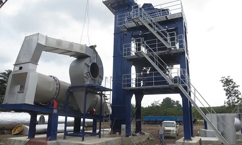
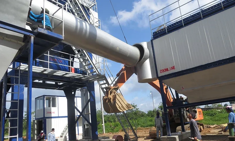
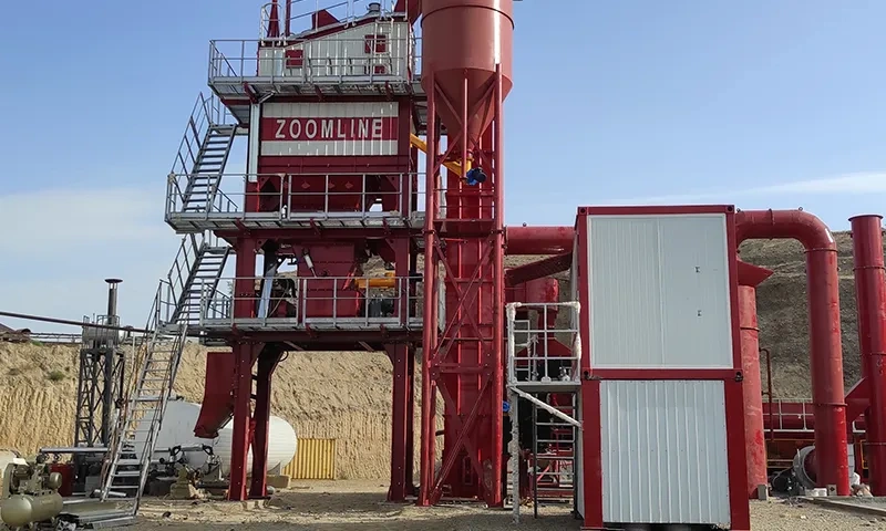
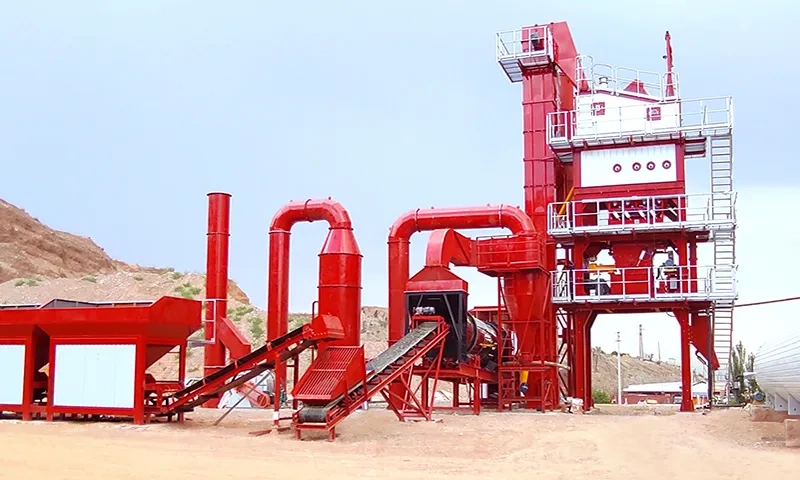
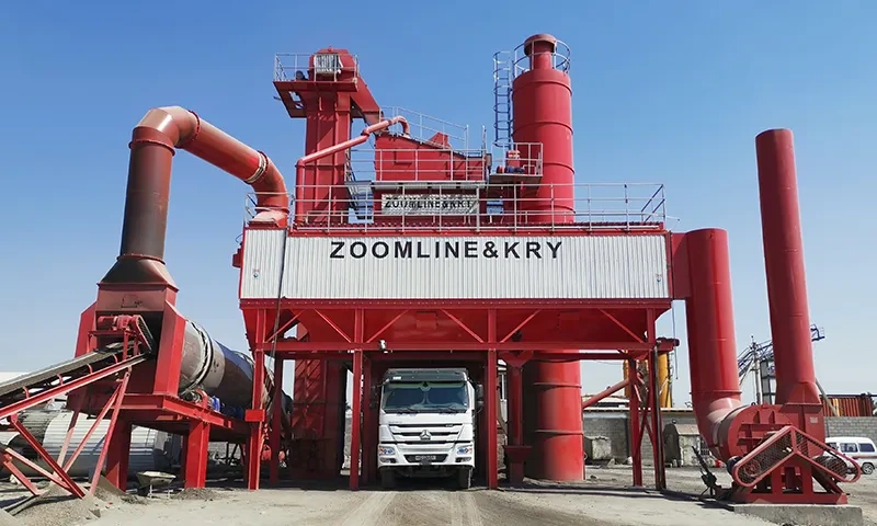
The production process of a continuous asphalt mixing plant operates linearly and continuously: First, aggregates are conveyed by belt conveyors to a screening system, where they are graded by particle size and then enter a drum dryer. Inside the drum, the hot airflow generated by fuel combustion comes into full contact with the aggregates, achieving moisture evaporation and heating (temperature rises to 120-180℃). The heated aggregates, along with metered asphalt and additives, enter the mixing section, where they are uniformly mixed during drum rotation. Finally, the finished asphalt mixture is discharged through the discharge port and either stored in a storage silo or transported directly to the construction site. Throughout the process, exhaust gases and dust are treated by a dust removal system before being discharged.
Main equipment components
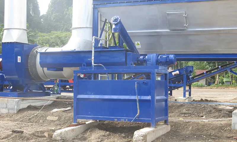
The core equipment includes: 1) an aggregate processing system (screening machine, belt conveyor), responsible for the grading and conveying of aggregates; 2) a drum dryer, serving as the core operating unit, realizing the dual functions of drying and mixing; 3) a combustion system (burner, fuel supply device), providing a heat source for drying; 4) an asphalt supply system (asphalt storage tank, metering pump), precisely controlling the amount of asphalt used; 5) a dust removal and environmental protection system (dust collector, induced draft fan, waste gas treatment device), treating pollutant emissions; and 6) a control system, which uses a PLC to achieve real-time control of production parameters.
Pollutant generation mechanism during production
Pollutant generation is highly correlated with each production stage: During aggregate drying, high temperatures release large amounts of mineral dust, which is the highest point (instantaneously reaching 200°C), making it a major source of particulate matter; during mixing, asphalt volatilizes upon heating, producing volatile organic compounds (VOCs), which combine with dust to form sticky pollutants; when the combustion system burns fuel, it generates gaseous pollutants such as CO, NOx, and sulfur oxides (SOx); during material loading, unloading, and transportation, uncollected fugitive dust is directly released into the atmosphere. Furthermore, sulfides and nitrogen oxides contained in the dust combine with moisture to form acidic substances, which are also corrosive.
Classification of dust removal technologies
Primary dust removal technology
Primary dust removal technology aims to remove large-diameter particles (typically >10μm) as a pretreatment step for subsequent processes. Its core principle is separation using gravity, inertia, or centrifugal force. The main technologies include gravity settling chambers, inertial dust collectors, and cyclone separators. Cyclone separators are the most widely used in asphalt plants due to their simple structure and low cost, and can reduce the dust load on subsequent equipment by 40%-60%. However, their removal efficiency for fine particulate matter (PM2.5) is relatively low (typically <50%).
Secondary dust removal technology
Secondary dust removal technology significantly improves efficiency for medium and fine particle sizes (1-10μm) and is a core component of dust removal systems in asphalt plants. Baghouse dust collectors (filter bag dust collectors) and electrostatic precipitators are the mainstream technologies. The former captures dust through filter media, achieving a PM2.5 removal efficiency of over 99%; the latter uses an electric field to adsorb charged dust, making it suitable for treating high-temperature, high-flow-rate exhaust gases, and achieving a fine particulate matter removal efficiency of over 95%. Both are often used alone or in combination to meet emission requirements.
Three-stage dust removal technology
Three-stage dust removal technology focuses on the synergistic treatment of ultrafine particulate matter (<1μm) and gaseous pollutants, and is key to achieving ultra-low emissions. It mainly includes wet scrubbers, activated carbon adsorption devices, and catalytic conversion equipment. Wet scrubbers capture dust and gaseous pollutants such as SOx and VOCs using water or chemical solutions, achieving “multi-purpose use of one device.” Activated carbon adsorption targets residual VOCs, further improving the purification effect of exhaust gas, and is typically used in areas with stringent environmental requirements.
Dust removal efficiency evaluation standards
Dust removal efficiency assessment requires comprehensive evaluation of multiple dimensions: First, particulate matter removal efficiency, calculated using the gravimetric method to determine inlet and outlet dust concentrations according to national standard GB/T 16157, the overall efficiency of the asphalt plant dust removal system must be ≥99.5%; Second, classification efficiency, for key particle sizes such as PM2.5, the removal effect of different particle sizes must be measured using a laser particle size analyzer; Third, operational stability, with continuous operating time and pressure loss fluctuation range as indicators, the pressure loss should be controlled within 1000-2000Pa under normal operating conditions; Fourth, environmental compliance, the emission concentration must comply with the “Integrated Emission Standard of Air Pollutants” (GB 16297) and stricter local standards (such as some regions requiring particulate matter emissions ≤10mg/m³).
Detailed Explanation of Common Dust Removal Equipment
Working principle of cyclone dust collector
Cyclone dust collectors operate on the principle of centrifugal separation: dust-laden airflow enters the cylinder tangentially through the inlet, forming a high-speed rotating airflow (linear velocity up to 12-20 m/s). Dust particles are thrown against the cylinder wall by centrifugal force and slide down the wall into the conical ash hopper. The purified airflow forms an upward vortex at the center and is discharged through the outlet. In its structural design, the cylinder diameter, inlet size, and cone angle directly affect the separation effect. Generally, a smaller cylinder diameter results in greater centrifugal force and higher dust removal efficiency, but the processing air volume is correspondingly reduced.
Advantages and disadvantages of cyclone dust collectors
Advantages include: simple structure, no moving parts, low manufacturing and maintenance costs; good temperature resistance, adaptable to high-temperature exhaust gases above 180℃ in asphalt plants; large air volume handling capacity, suitable as a primary dust removal device. Disadvantages mainly include: low removal efficiency for fine particulate matter (<5μm), insufficient to meet environmental protection requirements when used alone; significant pressure loss due to airflow rotation (typically 800-1500Pa), increasing induced draft fan energy consumption; and susceptibility to ash accumulation and blockage on the cylinder wall when handling sticky dust.
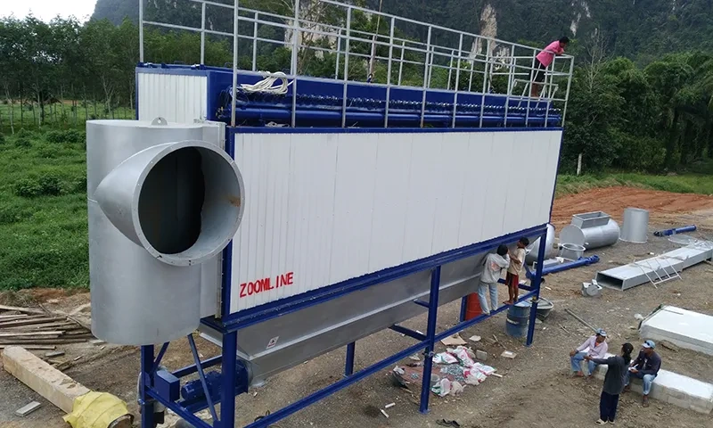
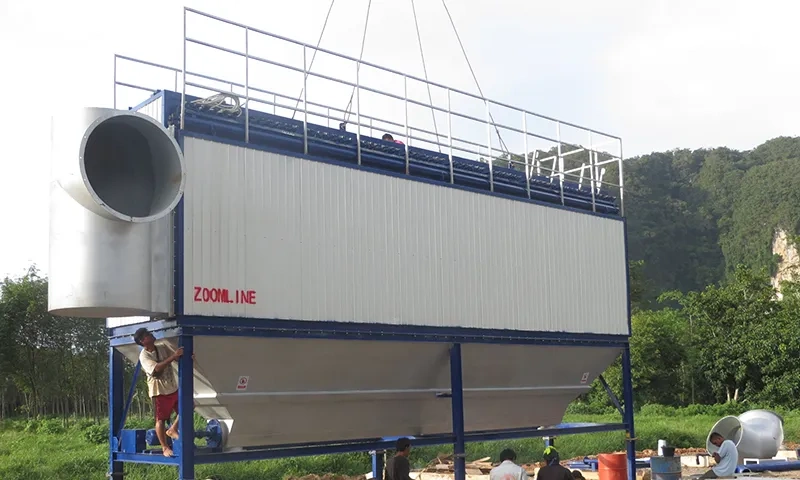
Structural Analysis of Bag Filters
A baghouse dust collector consists of a filter bag chamber, filter bag assemblies, a dust removal system, a dust hopper, and an induced draft fan. The filter bag chamber is a sealed box containing several filter bags (commonly round, 120-160mm in diameter and 2-6m in length), which are fixed to the tube sheet by clamps to form a filter layer. The dust removal system is available in three types: pulse jet cleaning, mechanical vibration cleaning, and reverse air cleaning. Pulse jet cleaning is the most widely used in asphalt plants due to its good cleaning effect and lack of disruption to continuous operation. The dust hopper is located at the bottom of the equipment and features a conical design for easy dust collection and discharge.
Filtration mechanism of bag filter
The filtration process is divided into two stages: the initial filtration stage, where dust-laden airflow passes through the filter bag, and dust particles are captured by the filter media surface through inertial collision, interception, diffusion, and electrostatic adsorption, gradually forming a “dust layer”; and the stable filtration stage, where the “dust layer” becomes the main filtration medium, significantly improving filtration accuracy, with the filter media primarily playing a supporting role. For the sticky dust from asphalt plants, modern filter media employ a three-layer protection technology: the surface layer is a dense filter layer formed by 0.8μm ultrafine fibers; the middle layer adds conductive fibers to prevent electrostatic adsorption; and the outer layer is impregnated with polytetrafluoroethylene (PTFE) to reduce surface energy, making it difficult for asphalt molecules to adhere, thus improving dust removal efficiency by more than 60%.
Application scenarios of electrostatic precipitators
Electrostatic precipitators are suitable for handling large-volume, high-temperature (withstanding temperatures above 300℃), and high-concentration dust, and are widely used in large-scale continuous asphalt mixing plants (daily capacity > 1000 tons). They are particularly suitable for high-temperature mineral dust generated during aggregate drying, as this type of dust has a moderate resistivity (10⁴-10¹¹Ω·cm) and is easily charged. Furthermore, for plants with high sulfur content in their fuels, the resulting acidic gases can reduce dust resistivity and improve dust removal efficiency. When a plant needs to simultaneously treat high-temperature exhaust gas and large amounts of dust, electrostatic precipitators offer excellent cost-effectiveness.
Key points for maintaining electrostatic precipitators
Key maintenance points include: First, regularly clean the dust collection plates by mechanical vibration or high-pressure water washing to remove accumulated dust and prevent excessive dust layers from affecting the electric field strength. Dust accumulation should typically be checked at least once a week. Second, check the perpendicularity and integrity of the discharge electrodes (corona wires). If bending or breakage is found, replace them promptly to prevent uneven electric field distribution. Third, monitor the power supply system to ensure the secondary voltage is stable at 40-60kV and the secondary current is 100-300mA, avoiding voltage fluctuations that could affect the charging effect. Fourth, ensure proper equipment corrosion protection by regularly applying anti-corrosion coatings to components such as plates and casings to prevent corrosion from acidic gases.
Technical characteristics of wet dust collectors
Wet scrubbers achieve dust capture and gas absorption by contacting the dust-laden airflow with water or a chemical solution. Their technical characteristics include: 1) strong synergistic processing capability, simultaneously removing particulate matter and gaseous pollutants such as SOx and VOCs, making them particularly suitable for high-sulfur fuel asphalt plants; 2) excellent handling of sticky dust, as the water film prevents dust from adhering to the equipment’s inner walls; 3) good temperature resistance, allowing direct treatment of high-temperature exhaust gases without the need for pre-cooling devices; and 4) moderate pressure loss (500-1000 Pa) and lower energy consumption than cyclone dust collectors. However, a wastewater treatment system is required to prevent secondary pollution.
Environmental impact of wet scrubbers
Positive impacts include: significantly reducing particulate matter and acid gas emissions, decreasing the risk of acid rain and smog formation; and achieving a PM2.5 removal efficiency of over 90%, improving regional air quality. Potential negative impacts include: direct discharge of dust-laden wastewater will pollute water bodies, requiring treatment through sedimentation tanks, filter presses, etc., to ensure suspended solids content ≤100mg/L before recycling or discharge; improper use of some chemical absorbents (such as alkaline solutions) may cause secondary pollution, necessitating precise control of reagent dosage and pH value (usually maintained at 8-10).
Design and optimization of dust removal systems
System layout planning
The layout should adhere to the principles of “nearby collection, short-path transportation, and easy maintenance”: dust hoods should be located close to dust generation points (such as the outlet of a rotary dryer or aggregate discharge port), employing a closed design to reduce fugitive emissions, with the hood opening velocity controlled at 1.5-2.5 m/s; dust collectors should be placed downwind of the prevailing wind direction, maintaining a distance of 10-15 m from the production workshop to prevent secondary dust diffusion; pipeline routes should be shortened as much as possible, reducing the number of bends (bend radius ≥ 3 times the pipeline diameter) to prevent dust accumulation and blockage. Sufficient maintenance space should also be reserved for filter bag replacement and equipment maintenance.
Air volume and air pressure calculation
Airflow calculations must cover all pollution points, using a “simultaneous operation factor”: Airflow at a single pollution point Q = 3600 × A × v (A is the hood area, m²; v is the hood velocity, m/s). The total airflow needs to consider a safety factor of 1.1-1.2. Taking a drum dryer as an example, if the outlet cross-sectional area is 1.2 m² and the hood velocity is 2 m/s, then the required airflow for a single unit is 3600 × 1.2 × 2 = 8640 m³/h. Air pressure calculations include pipe resistance, equipment resistance, and a safety margin. Pipe resistance is calculated by adding friction resistance and local resistance. Equipment resistance should refer to manufacturer parameters (e.g., baghouse dust collector resistance is approximately 1500 Pa). The total air pressure needs an additional 10%-15% margin.
Dust collection duct design principles
The pipeline design must meet the requirements of “anti-deposition and low resistance”: the pipe diameter is determined based on the air volume and velocity, with the velocity controlled between 18-22 m/s (the upper limit should be used for conveying sticky dust from asphalt plants) to avoid dust deposition due to excessively low velocities; circular pipes should be used, as their resistance is lower than that of rectangular pipes and they are less prone to dust accumulation; the pipe slope should be ≥3°, and a drain valve should be installed at the lowest point for easy cleaning of accumulated dust; pipelines for conveying dust of different particle sizes should be designed separately to prevent large dust particles from abrading or clogging smaller pipes. In addition, the pipelines must be insulated to prevent a sudden drop in exhaust gas temperature from causing asphalt to solidify.
Automation control integration
The automation system, centered on a PLC, integrates monitoring, control, and alarm functions: Dust concentration sensors monitor inlet and outlet dust concentrations in real time; when the outlet concentration exceeds the standard (>10mg/m³), the system automatically increases the induced draft fan’s airflow or activates a backup dust collector; pressure sensors monitor filter bag resistance; when the resistance exceeds 2000Pa, the system triggers a pulse cleaning system, with the cleaning frequency dynamically adjusted based on the resistance; temperature sensors monitor exhaust gas temperature in real time; if the temperature exceeds the filter material’s tolerance limit (e.g., PTFE filter material >200℃), the system automatically activates a cooling device or cuts off the feed; all data is uploaded to the central control system for remote monitoring and fault diagnosis.
Energy optimization strategy
Energy consumption optimization can be approached from several aspects: First, use variable frequency induced draft fans, adjusting the speed according to actual air volume requirements, which can save 20%-30% energy compared to fixed frequency fans; second, optimize the dust removal system, adopting an “on-demand dust removal” mode, controlling the dust removal timing through resistance sensors to avoid ineffective dust removal and energy consumption; third, select high-efficiency filter media to reduce filtration resistance and reduce the load on the induced draft fan; fourth, realize dust recovery and utilization, returning the collected dust to the mixing system to reduce raw material consumption; fifth, utilize waste heat from exhaust gas, recovering heat from high-temperature exhaust gas through heat exchangers to heat aggregates or asphalt, reducing fuel consumption.
Core elements of environmental protection technology
Exhaust gas emission control
The waste gas control adopts a “graded treatment + synergistic purification” mode: particulate matter is removed by a combination of “cyclone dust collector + bag filter” to ensure that the emission concentration is ≤10mg/m³; among gaseous pollutants, SOx is removed by wet scrubber (alkaline absorption) with an efficiency of over 85%; NOx is reduced to nitrogen by selective non-catalytic reduction (SNCR) technology, with an efficiency of ≥60%; VOCs are treated by activated carbon adsorption, and after adsorption saturation, they are thermally regenerated and recycled. Simultaneously, an online monitoring system (CEMS) is installed to monitor the emission concentrations of particulate matter, SOx, and NOx in real time, and the data is connected to the environmental protection department’s network.
Noise pollution prevention
Noise control is implemented from the perspectives of “source reduction, transmission blocking, and receptor protection”: Low-noise models are prioritized in equipment selection; for example, variable frequency induced draft fans reduce noise by 10-15 dB compared to traditional fans. Noise sources such as drum dryers and crushers are sealed and soundproofed, with sound-absorbing materials (such as centrifugal glass wool) installed inside the soundproof enclosures, which can reduce noise by 20-30 dB. Silencers are installed at the inlet and outlet of fans, and flexible connections are used in pipelines to reduce vibration noise. Sound barriers with a height of ≥3m are set up at the factory boundary, combined with greening for noise reduction (planting evergreen shrubs). Soundproof headphones are provided for operating positions to ensure that employee noise exposure complies with the “Industrial Enterprise Noise Hygiene Standard” (GBZ 2.2).
Wastewater treatment methods
The wastewater mainly includes drainage from the wet scrubber and equipment cleaning wastewater. The treatment process is as follows: first, large particulate impurities are removed by a screen, and then the wastewater enters a sedimentation tank for gravity settling. Polyaluminum chloride (PAC) coagulant is added to accelerate dust settling. The supernatant enters an air flotation tank to remove emulsified oil and fine suspended solids. Then, the wastewater passes through a biological treatment tank (using biological contact oxidation) to degrade organic matter. Finally, it is treated through a filtration tank and a disinfection tank to ensure that the effluent quality meets the Class I standard of the “Integrated Wastewater Discharge Standard” (GB 8978) (COD≤100mg/L, SS≤70mg/L). The treated wastewater can be recycled for use in the wet scrubber or for greening of the factory area, achieving zero discharge.
Solid waste recycling
Solid waste includes dust collected by dust collectors, waste filter bags, and asphalt slag. After screening, the portion of dust that meets the particle size requirements is returned to the asphalt mixing system to replace some aggregates, with a utilization rate of over 80%. Waste filter bags made of corrosion-resistant materials such as PTFE can be professionally recycled and regenerated, while ordinary filter bags are incinerated for harmless treatment. Asphalt slag is crushed and heated by recycling equipment and mixed with new aggregates and asphalt to produce recycled asphalt mixtures, with a recycling rate of ≥90%. Solid waste that cannot be recycled is sent to compliant landfills for disposal, ensuring a resource utilization rate of ≥95%.
Energy consumption reduction technology
Energy optimization technologies include: First, waste heat recovery, by installing a waste heat boiler at the exhaust outlet of the drum dryer, and using the generated steam to heat asphalt or provide heating, which can reduce fuel consumption by 15%-20%; Second, the use of new energy sources, by installing a photovoltaic power generation system in the plant area to supply power to auxiliary equipment (such as lighting and control systems), thereby reducing grid electricity consumption; Third, the optimization of the combustion system, by using low-NOx burners and precisely controlling the air-fuel ratio to improve fuel combustion efficiency and reduce CO emissions; Fourth, the promotion of warm-mix asphalt technology, which reduces the asphalt mixing temperature by 30-50℃, significantly reducing heating energy consumption and exhaust emissions.
Environmental applications of RAP recycled asphalt
Basic principles of RAP systems
RAP (Recycled Asphalt Pavement Material) systems produce recycled asphalt mixtures by recycling milled asphalt pavement material from old asphalt pavements. This material is then crushed, screened, heated, and mixed with new aggregates, new asphalt, and a recycling agent. The core principle is to replenish the lightweight components lost from the old asphalt using a recycling agent, restoring its viscoelasticity. Simultaneously, heating and stirring ensure uniform mixing of the old and new aggregates, guaranteeing that the recycled mixture meets design performance requirements. In continuous asphalt mixing plants, RAP is typically fed into a drum dryer simultaneously with the new aggregates via a dedicated feeding system, achieving coordinated heating and mixing.
RAP addition ratio and mixing technology
The RAP addition ratio is determined based on the properties of the recycled aggregate and the application scenario: when used in the subbase, the addition ratio can reach 40%-60%; when used in the surface layer, it needs to be controlled at 20%-30%, with 1%-3% recycling agent added. The mixing technology adopts a “segmented heating + precise metering” mode: the RAP feed temperature is controlled at 100-120℃ to avoid overheating and causing asphalt aging; the new aggregate is heated to 160-180℃, raising the overall temperature of the RAP through heat conduction; asphalt and recycling agent are precisely delivered using metering pumps to ensure a mixing ratio error of ≤±0.5%. Some advanced plants use a dual-roller system to heat the new aggregate and RAP separately, further improving the mixing quality.
RAP assessment of environmental benefits
The environmental benefits of RAP (Recycled Asphalt Powder) are significant: First, it saves resources. Every ton of RAP used reduces the mining of 0.8 tons of new aggregate and the consumption of 0.1 tons of new asphalt. Globally, RAP recycling can save tens of millions of tons of aggregate resources annually. Second, it reduces energy consumption. Producing recycled asphalt mixtures consumes 30%-40% less energy than producing new materials, reducing emissions from fuel combustion. Third, it reduces solid waste. If milled asphalt pavement is directly landfilled, it not only occupies land but also pollutes the environment. RAP can achieve 100% recycling, realizing the resource utilization of solid waste. Fourth, it reduces carbon emissions. Every ton of RAP used can reduce CO₂ emissions by about 0.3 tons, contributing to the achievement of the “dual carbon” target.
Dust removal challenges in RAP systems
RAP systems face unique dust removal challenges: First, the dust composition is complex. In addition to mineral dust, the RAP heating process releases aged components and impurities from old asphalt, resulting in higher dust viscosity and easier clogging of filter bags. Second, the dust has a high oil content, making it difficult to filter effectively with traditional filter media and hindering cleaning. Third, the moisture content of RAP fluctuates greatly; excessive moisture content leads to a decrease in exhaust gas temperature and asphalt condensation on the filter bag surface. To address these issues, PTFE-coated filter media should be selected to improve anti-sticking properties. Simultaneously, a dehydration device should be added before the dust removal system to control the RAP moisture content to ≤5%, and the cleaning frequency should be optimized.
Environmental regulations and standards
Overview of International Environmental Standards
Internationally, environmental standards for asphalt mixing plants are mainly coordinated regionally: the US EPA’s “Emission Standards for Asphalt Production” (40 CFR Part 60 Subpart I) stipulates that particulate matter emission concentrations should be ≤15 mg/m³ and NOx emission concentrations should be ≤180 mg/m³, while also requiring the installation of CEMS online monitoring; the International Organization for Standardization (ISO) has issued the ISO 14001 Environmental Management System standard, which provides an environmental management framework for asphalt plants; and the World Health Organization (WHO) has developed ambient air quality guidelines for PM2.5, recommending an annual average concentration of ≤5 μg/m³, and promoting countries to raise emission standards.
Comparison of EU emission standards
The EU’s emission standards are more stringent. Its Industrial Emissions Directive (IED 2010/75/EU) includes asphalt plants as a key industry for regulation, setting emission limits based on plant size: large asphalt plants (capacity > 50 tons/hour) must have particulate matter emissions ≤ 5 mg/m³, NOx ≤ 100 mg/m³, and SOx ≤ 50 mg/m³; small plants must have particulate matter emissions ≤ 10 mg/m³. Compared to US standards, the EU’s controls on NOx and SOx are stricter, requiring the implementation of “Best Available Technologies” (BAT), including the use of low-NOx burners and high-efficiency dust removal equipment. Furthermore, the EU requires asphalt plants to conduct carbon footprint accounting to promote low-carbon production.
Compliance testing methods
Compliance testing employs a combination of online monitoring and periodic sampling: online monitoring uses the CEMS system to collect particulate matter, SOx, NOx concentrations, and exhaust gas flow rates in real time, with data uploaded to the environmental protection department’s platform hourly to ensure the accuracy and validity of the monitoring data; periodic sampling is conducted by a third-party testing agency, determining particulate matter concentration using the gravimetric method as specified in GB/T 16157, and determining SOx and NOx concentrations using the chemical absorption method, with a sampling frequency of at least once per quarter; noise testing is conducted according to GB/T 12349, with monitoring points set up at the plant boundary, and monitoring conducted once during the day and once at night; wastewater testing is conducted according to GB/T 18920, with effluent water quality tested monthly.
Technical Challenges and Solutions
High-temperature dust removal problem
The temperature of exhaust gas from asphalt plants is typically 120-180℃, and can momentarily exceed 200℃, easily leading to aging and burnout of the filter media. Solutions include: first, selecting high-temperature resistant filter media, such as PPS fiber with a continuous temperature resistance of 190℃, P84 fiber with a resistance of 240℃, or PTFE-coated filter media with stable performance at 200℃; second, installing an exhaust gas cooling system, including a spray cooling device (using atomizing nozzles) at the dust collector inlet to control the temperature within the filter media’s tolerance range, with moisture generated during cooling discharged through a drain valve; and third, optimizing combustion control to avoid incomplete fuel combustion leading to localized high temperatures, ensuring exhaust gas temperature fluctuations are ≤±10℃.
Dust Adhesion Problem Handling
Dust adhesion originates from the mixing of asphalt fumes and dust, leading to filter bag clogging and cleaning failure. Solutions include: 1) Surface treatment of the filter media, using PTFE impregnation technology to reduce the surface energy of the filter media to 18 dyn/cm, thus reducing asphalt molecule adhesion; 2) Optimization of cleaning parameters, employing pulse jet cleaning with increased jet pressure to 0.4-0.6 MPa and extended jet time to 0.1-0.15 s to ensure dust layer shedding; 3) Controlling exhaust gas humidity, maintaining relative humidity between 30% and 50% to prevent excessive humidity from causing dust agglomeration; and 4) Applying an anti-sticking coating (such as PTFE) to the inside of the dust collection duct to prevent dust accumulation.
Equipment corrosion prevention
Sulfides and nitrogen oxides in dust combine with moisture to form acidic substances, which corrode the dust collector shell, pipes, and filter media. Prevention measures include: 1) using corrosion-resistant materials for the equipment, with the shell made of 316L stainless steel and the pipes made of fiberglass; 2) ensuring proper equipment insulation to prevent condensation from sudden drops in exhaust gas temperature, with an insulation layer thickness ≥50mm and using rock wool insulation material; 3) performing regular anti-corrosion treatment, applying an acid-resistant anti-corrosion coating (such as epoxy resin) to metal parts every six months; and 4) controlling the pH of the circulating water in the wet scrubber to 8-10 to neutralize acidic substances and reduce equipment corrosion.
System fault diagnosis techniques
Common faults and diagnostic methods: First, abnormally high dust collector resistance, if accompanied by a decrease in airflow, may indicate filter bag blockage. This can be confirmed by checking the operating status of the dust removal system and measuring the filter bag pressure difference. If accompanied by an increase in temperature, it may indicate pipe blockage. This can be located by using pressure sensors to detect pipe resistance in sections. Second, excessive dust emissions. If the outlet concentration suddenly increases, it may indicate filter bag damage. This can be confirmed by using a fluorescent powder detection method (spraying fluorescent powder at the inlet and detecting at the outlet). If the concentration gradually increases, it may indicate filter media aging. This can be confirmed by testing the air permeability of the filter media. Third, excessive vibration of the induced draft fan may be due to impeller dust accumulation or bearing wear. This can be confirmed by stopping the machine and checking the condition of the impeller and bearings.
Cost control and benefit balance
Cost control requires finding a balance between environmental protection investment and benefits: First, prioritize cost-effectiveness in equipment selection. Small and medium-sized factories can use a combination of “cyclone + bag filter” dust collection, while large factories can use a combination of “electrostatic + bag filter” to avoid excessive investment. Second, extend the life of vulnerable parts by regular maintenance (such as replacing filter bags every 2-3 years, which extends their life by 1 year compared to disorderly use) to reduce replacement costs. Third, strengthen resource recycling, increasing the dust recovery rate to over 90% and the RAP recycling rate to 30%, thus offsetting some of the environmental protection investment through raw material savings. Fourth, apply for environmental subsidies and take advantage of national support policies for environmental technology upgrades to reduce initial investment pressure.
Maintenance and Care Guide
Routine inspection items
Routine inspections (performed daily) include: 1. Monitoring the operating parameters of the dust removal system, including the induced draft fan current, inlet and outlet pressures, and exhaust gas temperature, to ensure these parameters are within the normal range; 2. Checking the filter bag status by using a differential pressure gauge to check the filter bag resistance, and promptly cleaning the filter bags if it exceeds 2000Pa; 3. Checking the cleaning system by verifying that the pulse valve’s blowing sound is normal and that the compressed air pressure is stable between 0.5-0.7MPa; 4. Checking the ash hopper discharge by confirming that the ash discharge valve is operating normally and that there is no material blockage; 5. Checking the online monitoring system by verifying that CEMS data is continuously uploaded and that the sensors are functioning properly.
Filter bag replacement process
Filter bags should be replaced every 2-3 years. The procedure is as follows: First, prepare for shutdown by turning off the induced draft fan, disconnecting the power, and opening the dust collector’s inspection door for ventilation for 30 minutes to ensure the internal temperature drops below 60℃. Second, remove the old filter bags by loosening the top clamps and taking the filter bags out of the tube sheet, taking care to avoid damaging the filter bags and causing dust to fall. Third, check the tube sheet and blowpipes, clean the accumulated dust in the tube sheet holes, and check whether the blowpipe nozzles are aligned with the filter bag openings. Fourth, install new filter bags by fitting them into the tube sheet holes and tightening the clamps to ensure a good seal. An airtightness test is required after the new filter bags are installed. Fifth, start the machine for commissioning by monitoring the filter bag resistance after starting the system to ensure there are no abnormalities.
Fan maintenance specifications
Fan maintenance is divided into regular maintenance and quarterly maintenance: Daily maintenance checks the fan vibration (vibration speed ≤4.5mm/s), bearing temperature (≤70℃), and sealing condition, ensuring there is no oil or air leakage; cleans the fan inlet filter weekly to prevent debris from entering the impeller; checks the belt tension monthly, adjusting or replacing it promptly if it is loose; performs in-depth maintenance quarterly, disassembling the fan to check for dust accumulation on the impeller and cleaning it; checks bearing wear and replenishes grease (using lithium-based grease); checks the clearance between the casing and the impeller, adjusting it promptly if the clearance is too large (>5mm).
Calibration of environmental monitoring instruments
Calibration of monitoring instruments ensures data accuracy. Calibration cycle and method: The CEMS system is calibrated quarterly. Particulate matter monitoring uses the standard dust concentration method, where standard dust of known concentration is passed into the sensor and the reading is adjusted to the standard value. SOx and NOx monitoring uses standard gas calibration, where standard gas at 50% of full scale is passed in, and the calibration error is ≤±5%. Noise monitors are calibrated every six months using standard sound calibrators (94dB, 114dB). Wastewater testing instruments (COD analyzer, SS analyzer) are calibrated monthly with standard solutions to ensure measurement accuracy.
Emergency Response Plan
Contingency plans are formulated for sudden environmental incidents: First, for emergencies of excessive exhaust emissions, immediately activate the backup dust collector, reduce production load, check for filter bags for damage, and replace them immediately if damaged; simultaneously report the situation to the environmental protection department, explaining the cause of the exceedance and the corresponding measures. Second, for equipment malfunctions, such as when the induced draft fan stops, immediately stop production, shut down the feeding system, open the bypass pipe to ensure temporary exhaust gas discharge (meeting emergency emission requirements), and organize maintenance personnel for emergency repairs. Third, for fire emergencies, if the filter bags burn due to high temperature, immediately cut off the power supply, activate the fire extinguisher (using dry powder fire extinguishers), and strictly prohibit the direct spraying of water onto high-temperature equipment; after the fire is extinguished, inspect the equipment for damage.
Future development trends
The Rise of Intelligent Dust Removal Systems
The intelligent dust removal system is based on the Internet of Things (IoT) and big data technologies to achieve automation of “perception-analysis-decision”: by deploying multi-dimensional sensors (temperature, pressure, dust concentration, filter bag status), it collects equipment operation data in real time; it uses edge computing modules to analyze data, predict filter bag life (error ≤10%), and judge failure trends; it optimizes the dust removal frequency and induced draft fan speed through AI algorithms, reducing energy consumption by 15%-20%; it supports remote operation and maintenance, and engineers can monitor equipment status through a mobile APP and remotely guide fault handling, reducing on-site maintenance costs.
The role of green materials in environmental protection
Green materials have become the core of environmental protection technology upgrades: In the field of filter media, biodegradable polylactic acid (PLA) based filter media has been developed, which can naturally degrade at the end of its service life, reducing solid waste pollution; in the field of catalysts, nano-titanium dioxide photocatalysts are used to activate catalytic reactions using ultraviolet light in waste gas, efficiently degrading VOCs with a degradation efficiency of ≥90%; in the field of regenerators, plant-based regenerators (such as soybean oil derivatives) have been developed to replace traditional petroleum-based regenerators, reducing environmental risks; and environmentally friendly glass wool is used for insulation materials, which does not contain formaldehyde or other harmful substances, improving the environmental quality of the factory area.
Low-carbon technology innovation
Low-carbon technologies focus on carbon emission reduction and carbon recovery: First, new energy substitution, using natural gas and biomass fuels to replace diesel, reducing CO₂ emissions by more than 30%; second, carbon capture technology, adding carbon capture devices after the exhaust gas treatment system, using amine solutions to absorb CO₂ with a purity of up to 99%, and using the captured CO₂ to make dry ice or inject it into oil fields for oil displacement; third, upgrading warm-mix asphalt technology, by adding nano-additives, reducing the mixing temperature to below 100℃, reducing energy consumption by 50%; and fourth, improving the carbon footprint accounting system to achieve full life-cycle carbon footprint tracking from raw material extraction to finished product transportation.
AI-assisted environmental optimization
AI technology enables precise control in environmental optimization: By analyzing historical operating data through machine learning algorithms, a correlation model between energy consumption and production parameters is established to optimize production load and environmental protection equipment operating parameters, reducing energy consumption per unit product by 10%; Computer vision technology is used to monitor fugitive dust emissions, cameras capture real-time images of the factory area, AI identifies areas with abnormal dust concentrations, and automatically triggers spray dust suppression devices; In RAP recycling, AI algorithms automatically calculate the amount of recycling agent and mixing ratio based on the performance parameters of the recycled material (such as penetration and ductility), improving the performance stability of the recycled material.
Global trend of sustainable development
Globally, the sustainable development of the asphalt industry exhibits three major trends: First, the integration of environmental standards, with countries gradually converging on the stringent standards of the European Union, driving the upgrading of environmental technologies in global asphalt plants; second, the deepening of the circular economy concept, with the target for RAP recycling rate increasing to over 50%, achieving a closed loop of “resource-product-recycled resources”; third, the construction of green supply chains, with owners prioritizing environmentally compliant companies in bidding, promoting the overall improvement of the industry’s environmental standards; and fourth, strengthened international cooperation, through technology exchange and transfer, helping developing countries improve the environmental capabilities of asphalt plants and jointly address global environmental challenges.
Conclusion
The dust removal and environmental protection technologies of continuous asphalt mixing plants are centered on “high-efficiency dust removal, synergistic pollution control, and resource regeneration”: The dust removal system adopts a “primary + secondary + tertiary” graded treatment mode, with bag filters becoming the core equipment due to their high removal rate of 99.9%, combined with PTFE coated filter media to solve the problem of high-temperature sticky dust; The environmental protection technology system covers all elements of waste gas, noise, wastewater, and solid waste, achieving full compliance through graded treatment of waste gas, noise insulation and reduction, wastewater recycling, and solid waste regeneration; RAP regeneration technology is the combination of environmental protection and efficiency, achieving resource recycling through precise control of the addition ratio and mixing technology.
Recommendations for industry development: First, enterprises should increase investment in environmental protection, prioritize the use of intelligent dust removal and low-carbon technologies, and upgrade the level of environmental protection equipment. Second, strengthen operation and maintenance management, establish a sound equipment maintenance and emergency response system, and ensure the stable operation of environmental protection facilities. Third, promote technological innovation, and collaborate with research institutions to develop high-temperature resistant, non-sticky, and biodegradable environmentally friendly materials and intelligent control systems. Fourth, industry associations should strengthen technical exchanges and training to improve the environmental awareness and technical skills of practitioners. In the future, with the deepening of intelligent technology and low-carbon concepts, continuous asphalt mixing plants will achieve the sustainable development goals of “high-efficiency production, ultra-low emissions, and recycling,” contributing to highway construction and environmental protection.