


What Is An Asphalt Mixer?
Contents
- 1 The Core Role of the Mixer in Asphalt Mixing Equipment
- 2 Main Components of the Mixing System
- 3 Structural Design Analysis of the Agitator
- 4 Core Functions and Performance Requirements of the Mixer
- 4.1 Ensuring Mixing Uniformity: Thorough Integration of Aggregates, Asphalt, and Fillers
- 4.2 Time Control: The Impact of Mixing Cycle on Production Efficiency and Mixture Quality
- 4.3 Temperature Maintenance: Controlling Heat Loss During Mixing
- 4.4 Wear Resistance and Durability: Meeting the Requirements of High-Abrasion Working Environments
- 4.5 Power Efficiency: Balancing Energy Consumption Control and Mixing Effect
- 5 Key Operating Points and Troubleshooting for Agitators
- 6 Maintenance and Upkeep System for Agitators
- 7 The Decisive Impact of Mixer Performance on Asphalt Mixture Quality
The Core Role of the Mixer in Asphalt Mixing Equipment
Standard Definition of an Asphalt Mixer
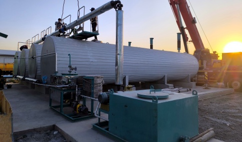
An asphalt mixer (also known as an asphalt agitator or asphalt mixture mixing device) is the core component of an asphalt mixing plant. It refers to specialized equipment that uses mechanical drive to rotate the mixing arms and blades, thoroughly mixing and homogenizing heated aggregates, asphalt, fillers, and additives according to a preset ratio to form an asphalt mixture that meets the quality requirements of road engineering. Its performance directly determines the homogeneity, stability, and various road performance indicators of the asphalt mixture, making it an indispensable key equipment in road construction and maintenance projects.
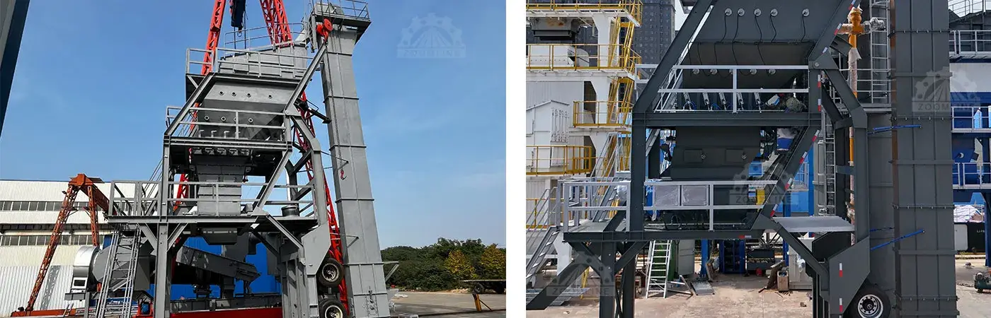
The Core Role of the Mixer in Asphalt Mixing Equipment
As the “heart” of the asphalt mixing equipment, the mixer undertakes the final core process of mixture preparation. Its role is irreplaceable throughout the entire asphalt production process. On the one hand, it needs to achieve precise blending of different materials to ensure the uniform distribution of components such as aggregates, asphalt, and fillers, avoiding quality problems such as segregation and uneven mixing, thus providing a qualified base material for road paving. On the other hand, the mixing process must balance efficiency and energy consumption, completing material mixing within a specified mixing cycle while controlling heat loss and power consumption, directly affecting the production efficiency, operating costs, and quality of the final mixture at the mixing plant. Furthermore, the stability and durability of the mixer determine the continuous operation capability of the entire mixing plant, reducing downtime and ensuring project progress.
Main Components of the Mixing System
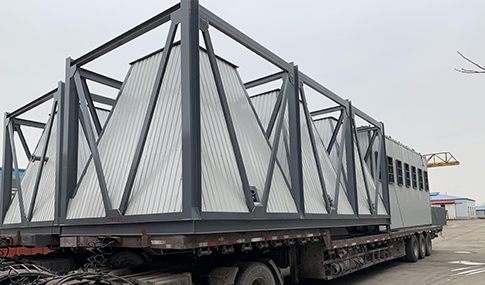
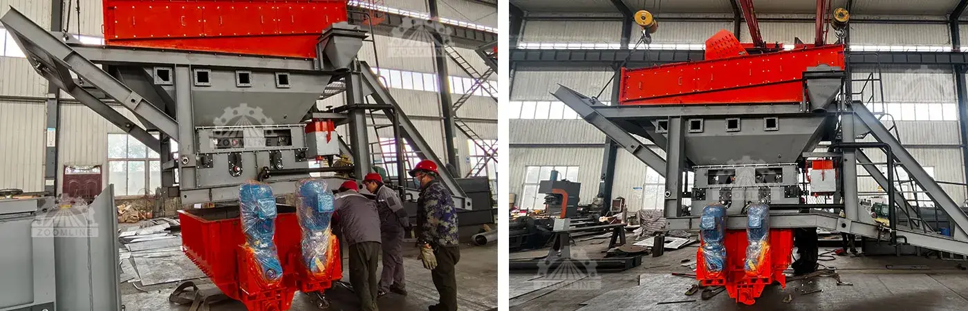
The mixing system of an asphalt mixer is a coordinated whole, mainly composed of the mixing cylinder, mixing devices (mixing arms and mixing blades), drive system, lubrication system, sealing system, and temperature control auxiliary device.
Mixing Unit (Cylinder): A sealed mixing container containing the mixing devices; it is the space where the mixing reaction occurs.
Mixing Drive System: Includes the main motor, reducer, coupling, etc., providing power for mixing.
Mixing Device: Consists of the mixing shaft, mixing arms, and mixing blades; it is the component that directly performs the mixing.
Liner System: Installed on the inner wall of the cylinder, protecting the cylinder from wear; typically made of wear-resistant steel plates.
Discharge Gate System: Controls the discharge of the finished mixture; requires rapid action and good sealing.
Lubrication System: Provides automatic or manual lubrication for moving parts such as bearings.
Detection and Control System: Monitors parameters such as current, temperature, and gate opening/closing status.
Structural Design Analysis of the Agitator
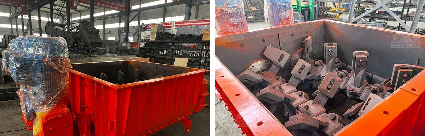
Detailed Explanation of the Internal Structure of the Agitator
Layout Design of the Agitator Arms (Direct and Reverse Installation Structures)
The layout of the agitator arms directly affects the material mixing trajectory and mixing efficiency. Common structures include direct and reverse installations.
In the direct installation structure, the agitator arms are arranged unidirectionally along the agitator shaft, clockwise (or counterclockwise). The blades push the material in a circular motion along the inner wall of the cylinder, simultaneously generating axial thrust, allowing the material to gradually mix during rotation. This structure is suitable for conventional mixing of ordinary asphalt mixtures and modified asphalt mixtures, featuring stable mixing and low energy consumption.
The reverse installation structure uses a bidirectional agitator arm layout. Some agitator arms push the material forward, while others block or push it in the reverse direction, creating convection and vortex flows, breaking the single motion trajectory, effectively reducing dead zones, and improving mixing uniformity. This structure is often used for mixing special asphalt mixtures with a high proportion of coarse aggregate and high material viscosity, but it requires higher driving power and has relatively higher energy consumption. In practical designs, a composite layout combining direct and reverse rotation is often used to balance mixing effect and energy consumption.
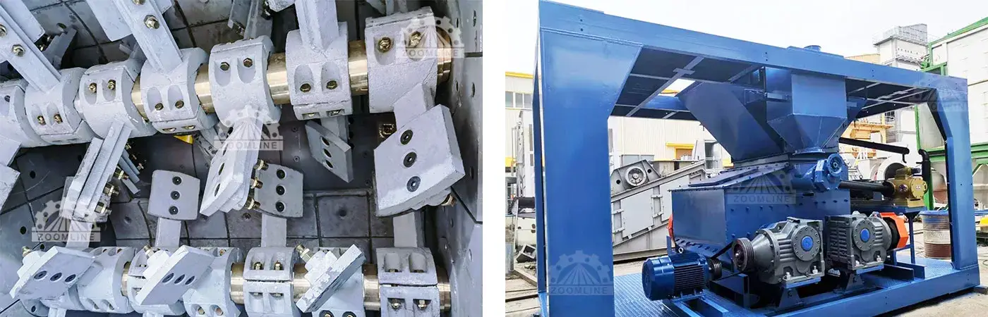
Agitator Blade Shape, Angle, and Arrangement
Agitator blades are the components that directly contact the material. Their shape is often rectangular or slightly curved, with edges frequently designed as replaceable wear-resistant alloy blocks. The blade installation angle (usually 30°-45° to the axis) determines the force and direction in which the material is pushed and thrown. Precise arrangement ensures no dead corners within the mixing tank, allowing all material to be effectively agitated and covered.
Liner Material and Protection Mechanism
Liners cover the inner wall of the mixing tank, withstanding the intense scouring and friction from the aggregate. They are typically made of high-strength wear-resistant alloy steel (such as NM400/500) or special wear-resistant cast iron. Liners are bolted in place and can be replaced individually after wear, making them a crucial “sacrificial component” for protecting the expensive tank. Advanced liner design optimizes their shape, aids material flow, and reduces material accumulation.
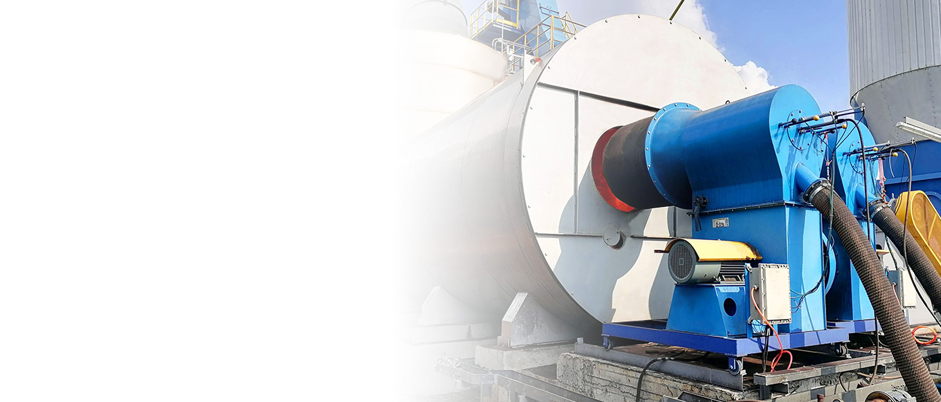
Drive System: Motor, Gearbox, and Transmission
The drive system provides powerful and stable power for agitation. A high-power motor (usually an asynchronous motor) drives a dedicated reducer via a coupling, with the reducer’s output shaft directly connected to the stirring shaft. This system requires high starting torque, smooth operation, and reliable durability. Some designs employ dual motors driving dual stirring shafts to achieve greater stirring capacity and power.
Core Functions and Performance Requirements of the Mixer
Ensuring Mixing Uniformity: Thorough Integration of Aggregates, Asphalt, and Fillers
Mixing uniformity is a core quality indicator of the mixture, requiring the elimination of segregation, whitening, and other issues. The mixer optimizes the blade structure to create a multi-dimensional material trajectory, controlling the rotation speed and cycle to ensure that asphalt evenly coats the aggregates and fills the gaps with fillers. For viscous materials such as modified and rubberized asphalt, the mixing effect can be improved by strengthening the mixing intensity, extending the cycle, or equipping with a forced mixing device to meet road quality requirements.
Time Control: The Impact of Mixing Cycle on Production Efficiency and Mixture Quality
The mixing cycle needs to balance production capacity and quality: too short a cycle leads to uneven mixing, while too long a cycle reduces efficiency, increases energy consumption, and may also cause asphalt aging. The cycle for ordinary asphalt mixtures is 30-60 seconds, while for modified and special mixtures it is extended to 60-90 seconds. The optimal value needs to be determined based on material characteristics and equipment performance tests, and precisely controlled through an automated control system to avoid human error.
Temperature Maintenance: Controlling Heat Loss During Mixing
Asphalt mixtures need to be mixed and paved within the 130-180℃ range, making heat loss control crucial. The mixer uses rock wool and aluminum silicate insulation layers on the outside of the cylinder to reduce heat loss, optimizes the structure to minimize contact between cold parts and hot materials, and controls the rotation speed to prevent excessive contact between materials and air. High-end equipment is equipped with an automatic temperature compensation device that activates when the material temperature drops below the set value to ensure temperature stability.
Wear Resistance and Durability: Meeting the Requirements of High-Abrasion Working Environments
The mixer must withstand aggregate impact, friction, and asphalt corrosion. In addition to using wear-resistant liners and high-strength boom blades, alloys are welded or hard alloys are inlaid in vulnerable areas. The mixing trajectory is optimized to reduce concentrated impacts, and high-quality seals prevent material from seeping into the internal components and causing corrosion. Components such as the boom shaft undergo strength calculations and fatigue tests to ensure they do not deform or break under long-term heavy loads, extending their service life.
Power Efficiency: Balancing Energy Consumption Control and Mixing Effect
The core of power efficiency is reducing energy consumption while ensuring effective mixing. The variable frequency energy-saving motor adjusts the speed as needed, the streamlined blade design and 3-5mm blade clearance reduce frictional resistance, and the high-efficiency reducer and coupling reduce power loss. In practical applications, it is necessary to optimize the stirring parameters to avoid over-stirring and energy waste, and achieve a balance between efficiency and performance.
Key Operating Points and Troubleshooting for Agitators
Pre-Start Inspection and Preparation
Check that the mixing tank is clean and free of foreign objects or solidified material.
Check that all inspection doors are closed and locked.
Confirm that the lubrication system oil level is normal, and manually lubricate the main bearings (if necessary).
Check the wear of the blades and liners, and tighten all bolts.
Perform a short test run, observing for any abnormal noises or jamming.
Monitoring Indicators During Operation
Monitoring of parameters such as current, noise, and vibration
Current: The main motor current is the core monitoring indicator. A stable current indicates a normal load. An abnormally high current may indicate overload, material jamming, or mechanical failure; a low current may indicate insufficient material or slippage.
Noise and Vibration: A regular stirring sound is present during normal operation. Sharp, muffled, or irregular impact sounds, or increased vibration, often indicate loose blades, detached liners, damaged bearings, or foreign objects entering the system.
Common Fault Diagnosis and Troubleshooting
Causes and Solutions for Uneven Mixture
Causes: Insufficient mixing time; severe blade wear or improper angle leading to insufficient mixing force; excessive temperature difference between aggregate and asphalt; incorrect feeding sequence or timing.
Solutions: Calibrate and ensure sufficient dry and wet mixing time; inspect and replace blades with excessive wear; strengthen temperature monitoring; verify the control system timing.
Troubleshooting Abnormal Noise and Vibration
Steps: Immediately stop the machine for inspection. First, check for any hard foreign objects (such as tools or maintenance parts) entering the cylinder. Then check if the mixing blades and liner bolts are loose or missing. Finally, check the reducer, bearing housings, and other transmission components.
Handling of Grout Leakage
“Groove leakage” usually refers to the leakage of fine powder or asphalt from the joints. Focus on checking if the sealing strip of the discharge gate is worn, aged, or contains foreign objects. Check the sealing condition of the mixing cylinder flange connections, observation windows, etc., and replace the seals promptly.
Maintenance and Upkeep System for Agitators
Daily Inspection and Maintenance Items
Blade and Liner Wear Inspection: Visually inspect every shift and measure wear periodically. Replace when 2/3 of the wear-resistant alloy layer is worn away or the base material begins to wear.
Lubrication System Maintenance: Regularly apply the specified grade of grease or lubricating oil to bearings, open gears, etc., as required by the instruction manual (e.g., every 8 hours, weekly, monthly). For automatic lubrication systems, check the oil level and pump operating status.
Fastener Condition Confirmation: Regularly (e.g., weekly) check and tighten bolts on critical components such as blades, liners, and agitator arms with a torque wrench to prevent loosening and detachment.
Critical Component Replacement Standards: Establish clear wear limit standards (e.g., blade wear, remaining liner thickness). Replace components when these standards are met to avoid damaging more expensive base components.
Wear Component Management and Replacement Strategy
Selection of Wear-Resistant Materials for Agitator Arms and Blades: Prioritize blades made of high-chromium wear-resistant cast iron or hard alloys such as tungsten carbide to extend service life several times over.
Liner Replacement Timing and Method: Liners must be replaced when they are cracked or worn to the point where the fixing bolt heads are about to be exposed. During replacement, the mounting surface should be cleaned, anti-loosening bolts should be used, and tightening should be even. It is recommended to replace in groups or as a whole ring to ensure uniform clearance.
Seasonal Shutdown Maintenance Precautions
After the production season ends, all residual material inside and outside the mixing tank must be thoroughly cleaned.
Perform comprehensive lubrication maintenance on all lubrication points.
Inspect and record the wear condition of all vulnerable parts to provide a basis for spare parts planning for the next production season.
Take measures to prevent moisture and dust from entering the motor and electrical cabinet.
If the shutdown period is long, the mixing shaft should be rotated periodically to prevent rust and seizing of the bearings.
The Decisive Impact of Mixer Performance on Asphalt Mixture Quality
The performance of the mixer directly determines the quality of the mixture and the service life of the road. A high-quality mixer can improve the bond strength and durability of the mixture, reducing pavement distress; insufficient performance leads to mixture defects and premature pavement damage. Optimizing mixer application is key to improving the efficiency of the mixing plant. This includes selecting an appropriate boom and blade layout based on the mixture type, employing intelligent systems for precise temperature and time control, establishing a comprehensive maintenance system to reduce downtime, and strengthening personnel training to standardize operation. Through these measures, mixer efficiency can be maximized, improving the mixing plant’s capacity, quality, and profitability.